V5 series inverter
24
(Inverters and motors are all grounded well)
If the communication is still failed with the above connection methods, you can adopt the following methods:
(1) Use separate power supply for PLC or isolate its power supply.
(2) Use magnetism ring for the cable and reduce the inverter’s carrier frequency.
2-6. Mounting guide according with EMC
As the inverter output wave is PWM, electromagnetic noise will generate while it is working. To reduce the inverter inter-
ference for other devices, this chapter introduces the EMC mounting method in the following aspects: control the noise,
local wiring, grounding, leak current, power supply filter.
2-6-1. Control the noise
1. Noise type
The noise made by inverter may affect the neaby equipments and the effection is related to inveter’s control system, anti-
noise and anti-jamming ability of the devices, wiring environment, safety distance, grounding method and other fac-
tors.The noise contains the following types: electrostatic induction, circuit transmit, space transmit, electro magnetic in-
duction and so on.
2. Essential countermeasure for suppressing noise
Table 2-5 solution for control noise
Noise transmit
path
Solution
2
When the ground cable of external equipment forms a loop with the inverter, the equipment may operate incor-
rectly caused by leakage current of inverter grounding cable. The problem can be solved if the equipment is not
grounded.
3
If the external equipment shares the same AC supply with the inverter, the inverter’s noise may be transmitted
along its input power supply cables, which may cause interference to other external equipments. Take the follow-
ing actions to solve this problem: Install noise filter at the input side of the inverter, and use an isolation trans-
former or power filter to prevent the noise from disturbing the external equipment.
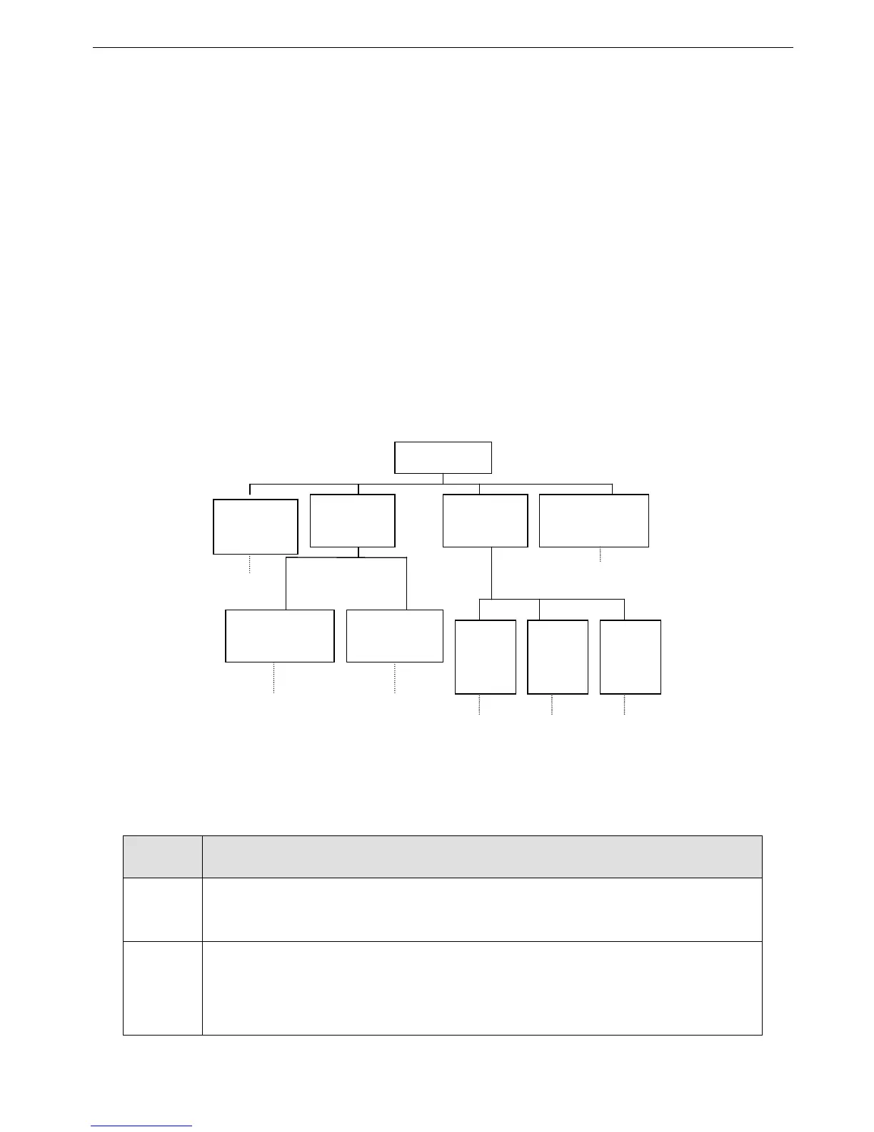
Noise types
Circuit
transmission
Space
transmission
Electromagnetic
induction
Leakage current
grounding circuit
Power supply
transmission
Path 2 Path 3
Path 7, 8
Motor
cable
RF
Power
cable
RF
Inverter
radia-
tion
Path 4 Path 6
Electrostatic
induction
Path 1
Path 5