V5 series inverter
16
2-2. Wiring
Wiring after power off for at least 10 minutes, otherwise, an electronic short may occur.
Do not connect AC power to output terminals U, V and W.
Both the inverter and the motor should be safety grounded as there is leakage current inside the inverter.The diameter
of grounding copper cable must be more than 3.5mm², grounding resistor must be less than 10ohm.
Withstand voltage test of the inverter has been done in the factory, users would better not do it again.
Do not install electromagnetic contactor, absorption capacitor or other resistance-capacitance absorption devices, as
shown in Fig2-3.
In order to make the input over-current protection and power off maintenance easily, the inverters should connect
power supply via braker.
The connection cable of relay I/O circuit (X1~X6, FWD, REV, OC, DO) should select the twisted-pair or shield cable
with diameter over 0.75 mm². One terminal of the shield layer should be hung in the air and the other terminal should
be connected with the inverter’s grounding terminal E, the cable length should be less than 50m.
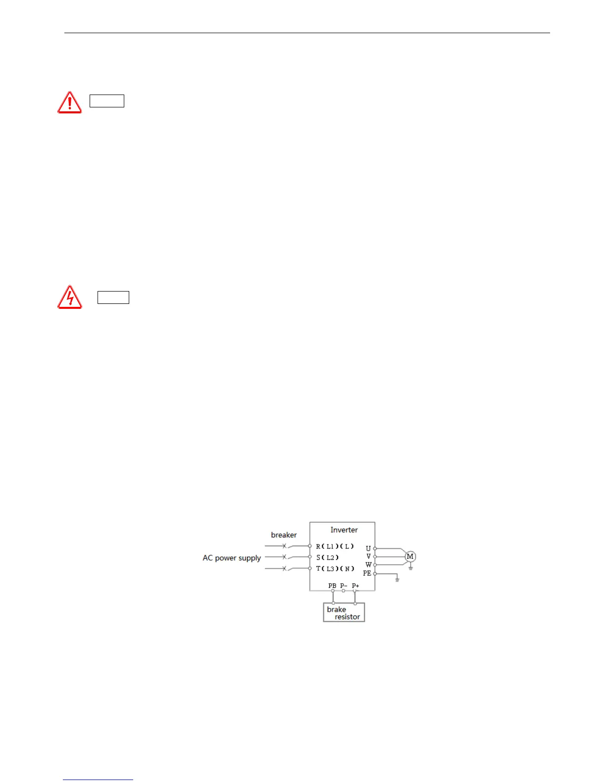
2-3. Wiring of main circuit terminals
2-3-1. Wiring diagram
Fig. 2-3 Wiring of main circuit
Caution
Danger
Before layout operation, make sure the power supply of inverter is cut off, all the LED on the operate panel is black out
and delay for more than 10 minutes.
Wiring work can be performed after the voltage between internal electrolesis capacity “+” and “–” is below DC36V.
Wiring work can only be done by trained and professional personnel.
Before power on, please check if the power supply voltage is consistent with the inverter voltage level, otherwise
device damage, human injuries and deaths may occur.