V5 series inverter
25
4,5,6
(1)The equipment and the signal cables should be far away from the inverter. The signal cables should be
shielded and the shielding layer should be grounded. The signal cables should be located far away from the in-
put/output cables of the inverter. If the signal cables must cross over the power cables, they should be placed at
right angle to one another.
(2) Install high-frequency noise filter (ferrite common-mode choke) at the input and output of the inverter to pre-
vent the RF interfere of power lines.
(3) Motor cables should be placed in a tube thicker than 2mm or buried in a cement slot. Power cables should be
placed inside a metal tube and be grounded by shielding layer (Motor cable should use 4-core cable, one of the
cores should be grounded near the inverter and another point should be connected to the motor’s cover).
1,7,8
Don’t put the strong and weak electricity cables in parallel or bundle these cables together. Other devices should
also be away from the inverter.The devices wire should be away from the I/O of the inverter. The signal cables
and power cables should be shielded cables. Devices with strong electric field and magnetic field should be away
and orthogonal from the inverter.
2-6-2. Local wiring and grounding
(1) The cable connected inverter and motor (cables from U, V, W points) should not parallel with power supply calbe (R, S,
T or L, N terminal input wire). The distance should be more than 30cm.
(2) Inverter’s output cables from U, V, W terminals is recommend to put in metal tube or slot.
(3) Control signal cables should be shield and the shield layer should be connected with inveter’s PE terminal, then ground
the point near the inverter.
(4) The grounding cable of inverter’s PE terminal should be connected to ground directly.It can’t connect to other devices’
grounding cables.
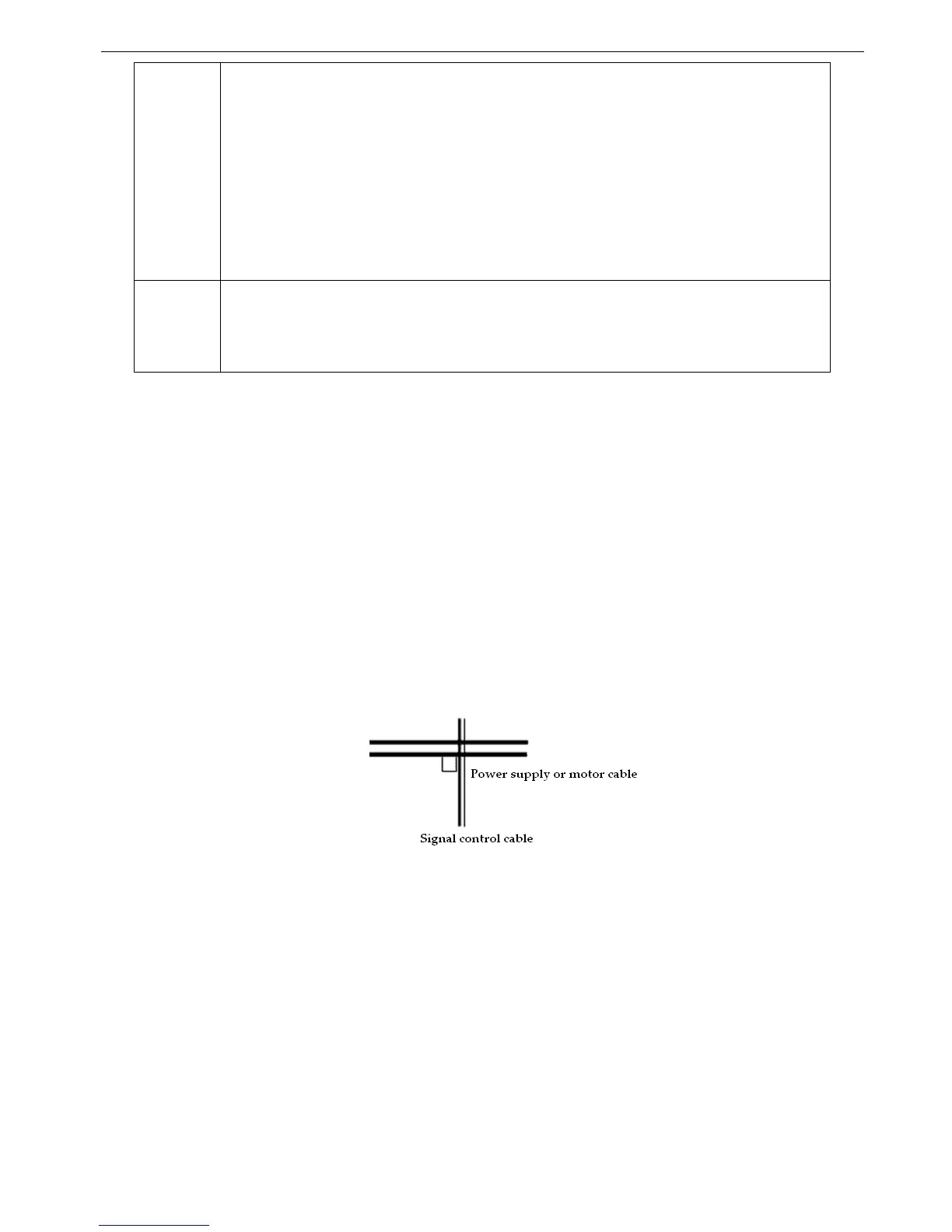
(5) Don’t put the signal cables in parallel with the power cables (R, S, T or L, N with U, V, W) or bundle these cables to-
gether, at least 20~60 cm distance shoule be kept (related with power current), If the signal cables and power cables
needed to be intersected, they should be vertical to each other, as shown in Fig2-12.
Fig. 2-12 Wiring requirement of system
(6) The weak electricity grounding cable such as control signal and sensors should be separated with strong electricity
grounding cable.
(7) Do not connect other devices to inverter’s power input terminals (R, S, T or L, N).