V5 series inverter
56
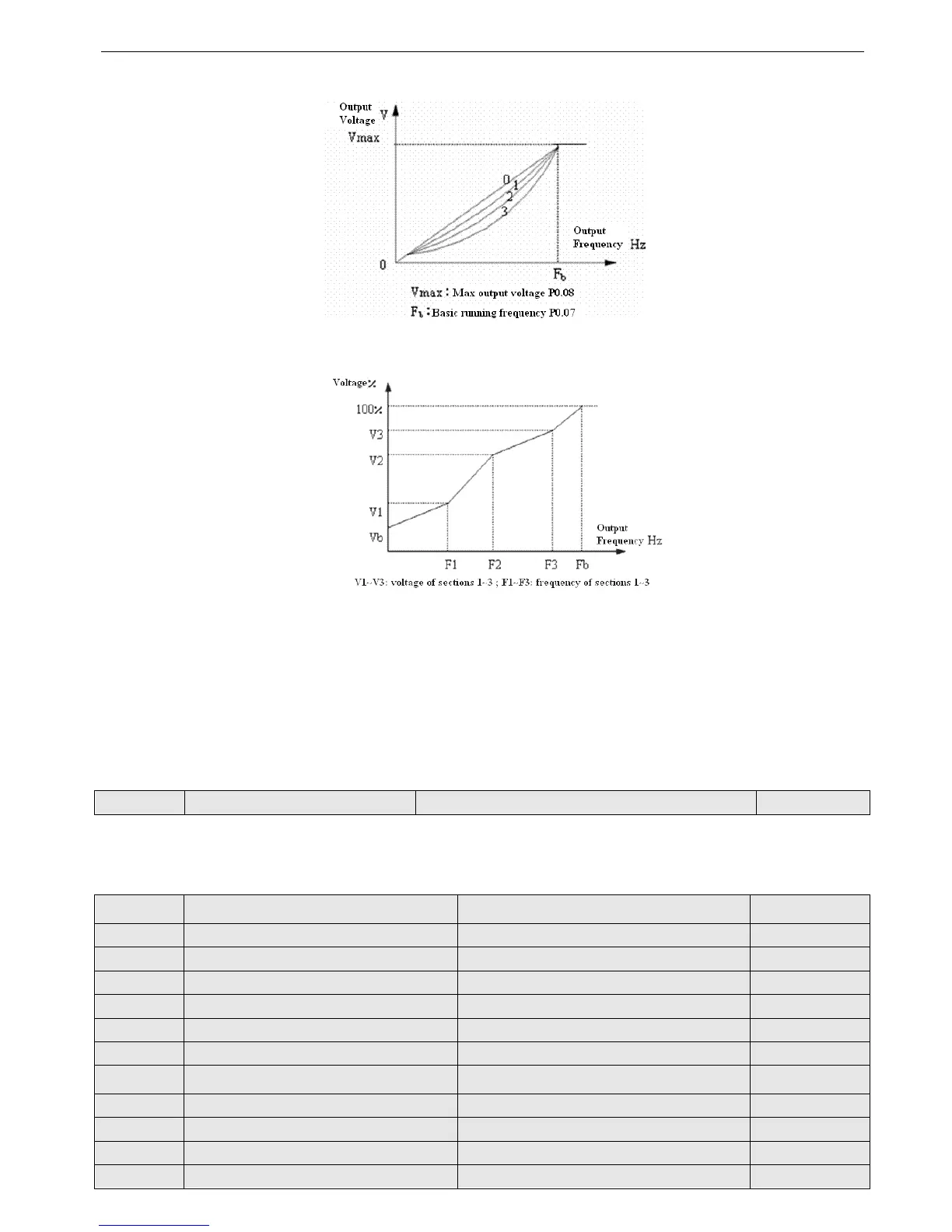
To obtain the best energy-saving effect, user can select V/F curve 1, 2, 3 for fan, pump load.
Fig.4-7 V/F curve
Fig. 4-8 User-defined V/F curve
When P0.22 = 4, you can define V/F curve via modifying (V1, F1), (V2, F2), (V3, F3) to satisfy the special load require-
ment, as shown in Fig.4-8. Torque boost is suitable for user-defined V/F curve. In Fig.4-8.
Vb =Torque boost(P0.09)× V1
4-2-2. Parameters of frequency setting (Group P1)
P1.00 Time constant of analog filter Range: 0.01~30.00s 0.20s
The inverters filter time for sample value when set the frequency by analog channel. If the wiring is too long or noise is too
serious, increase this parameter to improve the frequency stability. The longer the filter time, the stronger the noise immun-
ity ability. However, the reponse will be slower.
P1.01 The gain of VI channel Range: 0.01~9.99 1.00
P1.02 Min setting of VI Range: 0.00~P1.04 0.00V
P1.03 Frequencyof VI min setting Range: 0.00~upper limit of frequency 0.00Hz
P1.04 Max setting of VI Range: P1.04~10.00V 10.00V
P1.05 Frequency of VI max setting Range: 0.00~upper limit of frequency 50.00Hz
P1.06 Gain of CI channel Range: 0.01~ 9.99 1.00
P1.07 Min setting of CI Range: 0.00~ P1.09 0.00V
P1.08 Frequency of CI min setting Range: 0.00~upper limit of frequency 0.00Hz
P1.09 Max setting of CI Range: P1.07 ~10.00V 10.00V
P1.10 Frequency of CI max setting Range: 0.00~upper limit of frequency 50.00Hz
P1.11 Max input pulse frequency of PULSE Range: 0.1~20.0K 10.0K
P1.12 Min setting of PULSE Range: 0.0~P1.14 0.1K