72
Fig.
Fig.
Fig.
Fig. 4-23
4-23
4-23
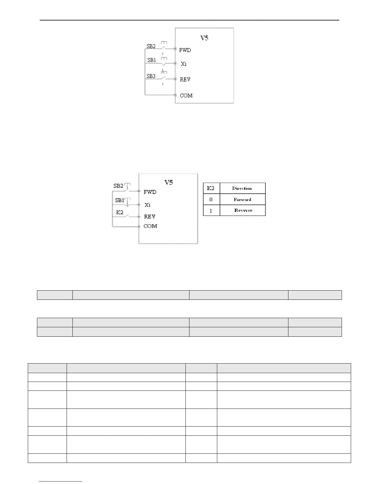
4-23 3-wire
3-wire
3-wire
3-wire operation
operation
operation
operation mode
mode
mode
mode 1
1
1
1
Xi is the multi-function input terminal of X1~X6
,
here you should define its function as N o.9 “ 3-wire control mode ” .
3
3
3
3 : 3-wire
3-wire
3-wire
3-wire control
control
control
control mode
mode
mode
mode 2
2
2
2
SB1 : Stop button
SB2 : Running button
Fig.
Fig.
Fig.
Fig. 4
4
4
4 -24
-24
-24
-24 3-wire
3-wire
3-wire
3-wire control
control
control
control mode
mode
mode
mode 2
2
2
2
Xi is the multi-function input terminal of X1~X6 , here you should define its function as No.9 “ 3-wire control mode ” .
Note
Note
Note
Note : When the inverter stops due to fault, it will start immediately if the terminal control mode and terminal FWD/REV
are enabled and the fault is cleared.
This parameter defines the change rate of reference frequency that is changed
by
UP/DOWN.
Bi-direction oper-collector output termin al OC , the options of this parameter are shown in Table 4-6 .
Table
Table
Table
Table
4-6
4-6
4-6
4-6 Functions
Functions
Functions
Functions of
of
of
of output
output
output
output terminals
terminals
terminals
terminals
UP/D
UP/D
UP/D
UP/D OW
OW
OW
OW N
N
N
N speed
speed
speed
speed rate
rate
rate
rate
Range
Range
Range
Range : 0.01
0.01
0.01
0.01 ~ 99.99H
99.99H
99.99H
99.99H z/s
z/s
z/s
z/s
1.00
1.00
1.00
1.00 H
H
H
H z/
z/
z/
z/ s
s
s
s
Bi-direction
Bi-direction
Bi-direction
Bi-direction open-collector
open-collector
open-collector
open-collector output
output
output
output terminal
terminal
terminal
terminal OC
OC
OC
OC
Range
Range
Range
Range : 0
0
0
0 ~ 20
20
20
20
Relay
Relay
Relay
Relay output
output
output
output selector
selector
selector
selector
Range
Range
Range
Range : 0
0
0
0 ~ 20
20
20
20
Setting
Setting
Setting
Setting
Functions
Functions
Functions
Functions
Setting
Setting
Setting
Setting
Functions
Functions
Functions
Functions
PLC is finished after one cycle running
Frequency arriving signal (FAR)
Specified counting value arriving
Frequency detection threshold (FDT1)
Mid counting value arriving
Frequency detection threshold (FDT2)
Inverter Ready running finished ( RDY )
Overload pre-alarm ( OL )
Inverter under voltage locking ( LU )
Start frenquence running time
External fault stop ( EXT )
Start DC injection braking time
 Loading...