82
After start command is set out, the motor will start and accelerate to the frequency in the Acc time until the setting frequency
reach or exceeds the certain value
Fb
.
Stop process :
The inverter will not stop immediately if the setting frequency is lower than Fb, only when the setting frequency reach Fa,
the inverter will stop output.
Fa points to zero-frequency threshold which is defined
by
P7.18, the value among Fb-Fa point to zero-frequency hysteresis
which is defined
by
P
7.19
.
This function can enable the inverter to enter domant state so as to save energy, besides, the inverter will not start at the
threshold of zero-frequency operation if the hysteresis is set properly.
4-2-9
4-2-9
4-2-9
4-2-9
.
.
.
.
Simple
Simple
Simple
Simple PLC
PLC
PLC
PLC operation
operation
operation
operation parameters
parameters
parameters
parameters .
.
.
. ( Group
Group
Group
Group P8
P8
P8
P8 )
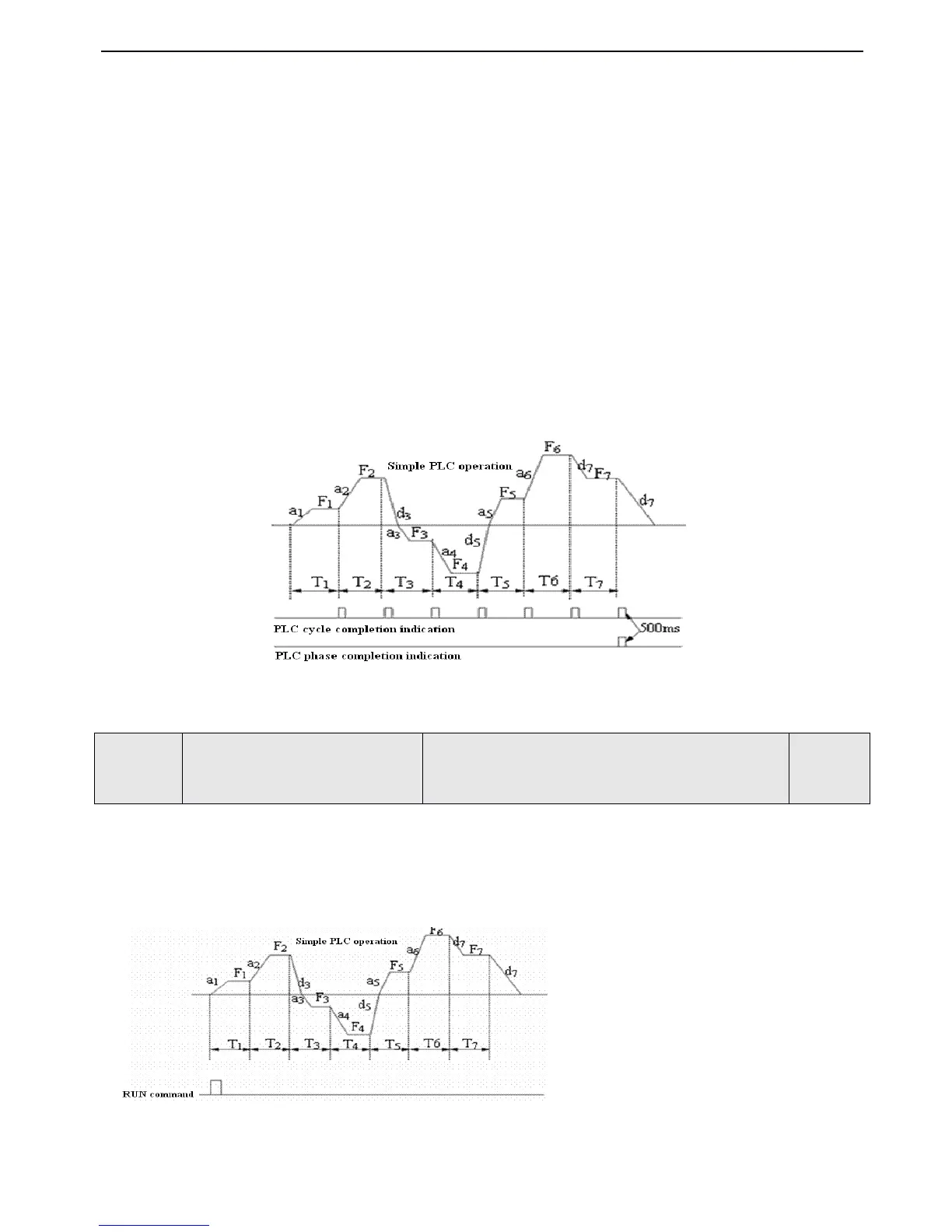
Simple PLC function can enable the inverter to change its operating frequency and directions automatically to satisfy the
manufacturing requirements
,
as shown in Fig4-40.
Fig.
Fig.
Fig.
Fig. 4-40
4-40
4-40
4-40 Simple
Simple
Simple
Simple PLC
PLC
PLC
PLC diagram
diagram
diagram
diagram
In Fig,4-40 , a
1
~a
7
、 d
1
~d
7
are the Acc/Dec time of different stages and they are set
by
Acc/Dec time parameters P0.17 , P0.18
and P3.14 ~
P3.2
,
F
1
~F
7
、 T
1
~T
7
are the running frequency and running time and they are set
by
P8.01 ~ P8.14 .
Unit
Unit
Unit
Unit
’
’
’
’
s
s
s
s place
place
place
place of
of
of
of LED
LED
LED
LED : PLC operation mode selection
0
0
0
0 : Disabled.
Disabled.
Disabled.
Disabled.
1
1
1
1
:
Stop
Stop
Stop
Stop after
after
after
after operating
operating
operating
operating for
for
for
for one
one
one
one cycle.
cycle.
cycle.
cycle. As
As
As
As shown
shown
shown
shown in
in
in
in Fig.4-41
Fig.4-41
Fig.4-41
Fig.4-41
.
If inverter stop after single cycle operation
,
running comma nd
should be give once again to start the inverter.
Fig.
Fig.
Fig.
Fig. 4-41
4-41
4-41
4-41 PLC
PLC
PLC
PLC stop
stop
stop
stop mode
mode
mode
mode after
after
after
after single
single
single
single cycle
cycle
cycle
cycle of
of
of
of operation
operation
operation
operation
2
2
2
2
:
Holding at the final value after single cycle of operation
.
.
.
.
A s shown in Fig. 4-42
,
Inverter will keep the running frequenc
y,
direction of the last setting automatically after single cycle is completed
,
then it will stop with the reference Dec time if stop
 Loading...