66
These frequencies will be used in multi-step speed operation and simple PLC operation, please refer to the instructions of
P4.00~P4.05 and
P8
.
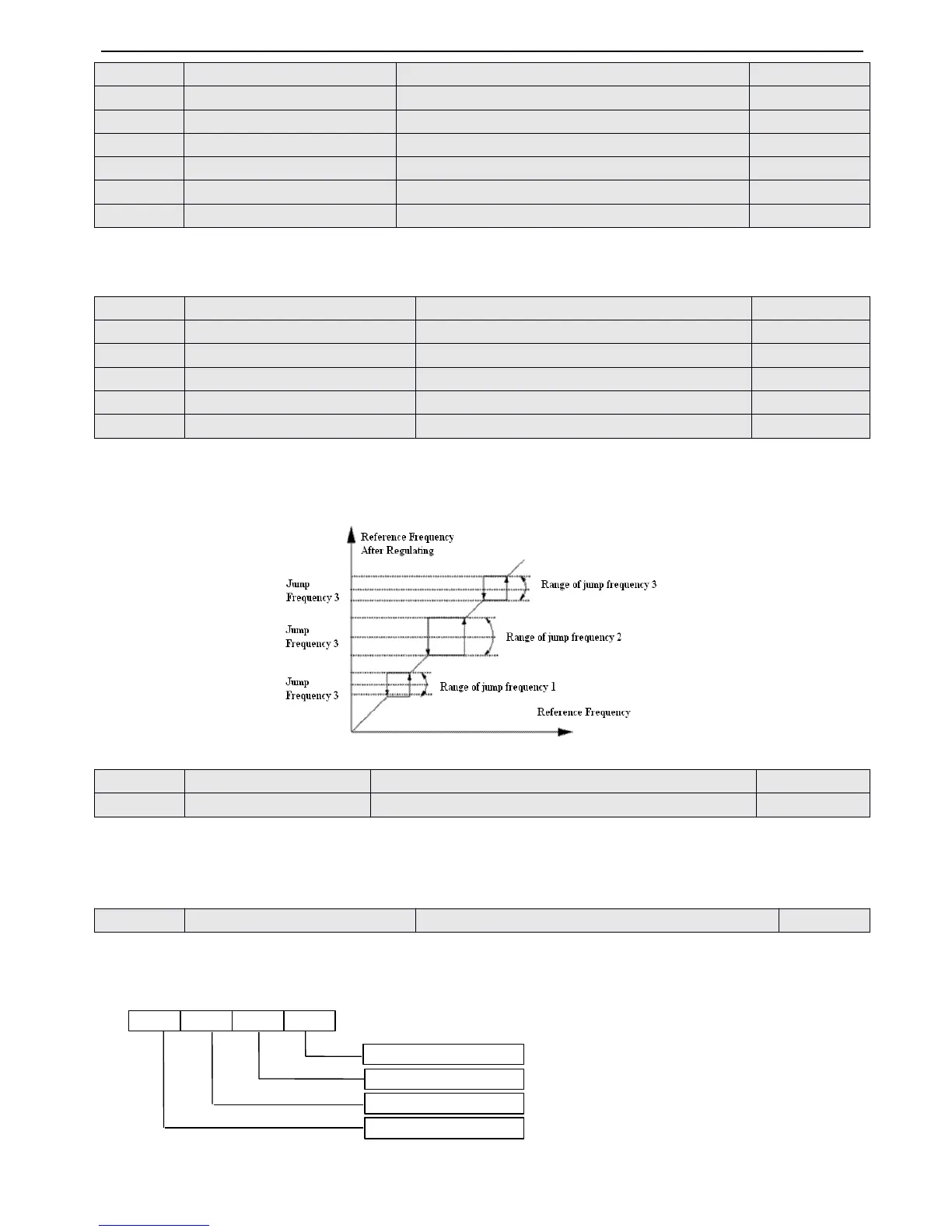
P3.33~P3.38 define the functions that will let output frequency of the inverter avoid resonant point of mechnical load. The
reference frequency of the inverter can do jump operation in the certain range of some jump frequency point, as shown in
Fig
.
6-15
,
you can define three ranges of jump frequency at most.
Fig.
Fig.
Fig.
Fig. 4-15
4-15
4-15
4-15 Jump
Jump
Jump
Jump frequency
frequency
frequency
frequency and
and
and
and rang
rang
rang
rang e
e
e
e
Acculate run ning time to reach the reference time ( P3.39 )
,
the inverter will output signal, refer to function instruction of
P4.08~P4.09 .
P3.40 refers to the accu mu lating running time from factory till now.
P3.41 cont rols that if the monitor parameter s b-09 ~ b-24 can be displayed in parameter group
by
four figures
.
T he
parameter values are in
h
ex which should be changed to binary ones according to the sequence of monitor parameters when
using. The relationship between four figures and parameters are shown in Fig.4-16.
Fig.
Fig.
Fig.
Fig. 4
4
4
4 - 16
16
16
16 Display
Display
Display
Display parameters
parameters
parameters
parameters selection
selection
selection
selection 1
1
1
1
Note:
Note:
Note:
Note: A:
A:
A:
A: Thousand
Thousand
Thousand
Thousand
’
’
’
’
s
s
s
s place,
place,
place,
place, B:
B:
B:
B: Hundred
Hundred
Hundred
Hundred
’
’
’
’
s
s
s
s place,
place,
place,
place,
 Loading...