84
Fig.
Fig.
Fig.
Fig. 4-44
4-44
4-44
4-44 PLC
PLC
PLC
PLC start
start
start
start mode
mode
mode
mode 1
1
1
1
Ten
Ten
Ten
Ten
’
’
’
’
s
s
s
s place
place
place
place of
of
of
of LED
LED
LED
LED : Save at power off
0
0
0
0 : Not
Not
Not
Not saving.
saving.
saving.
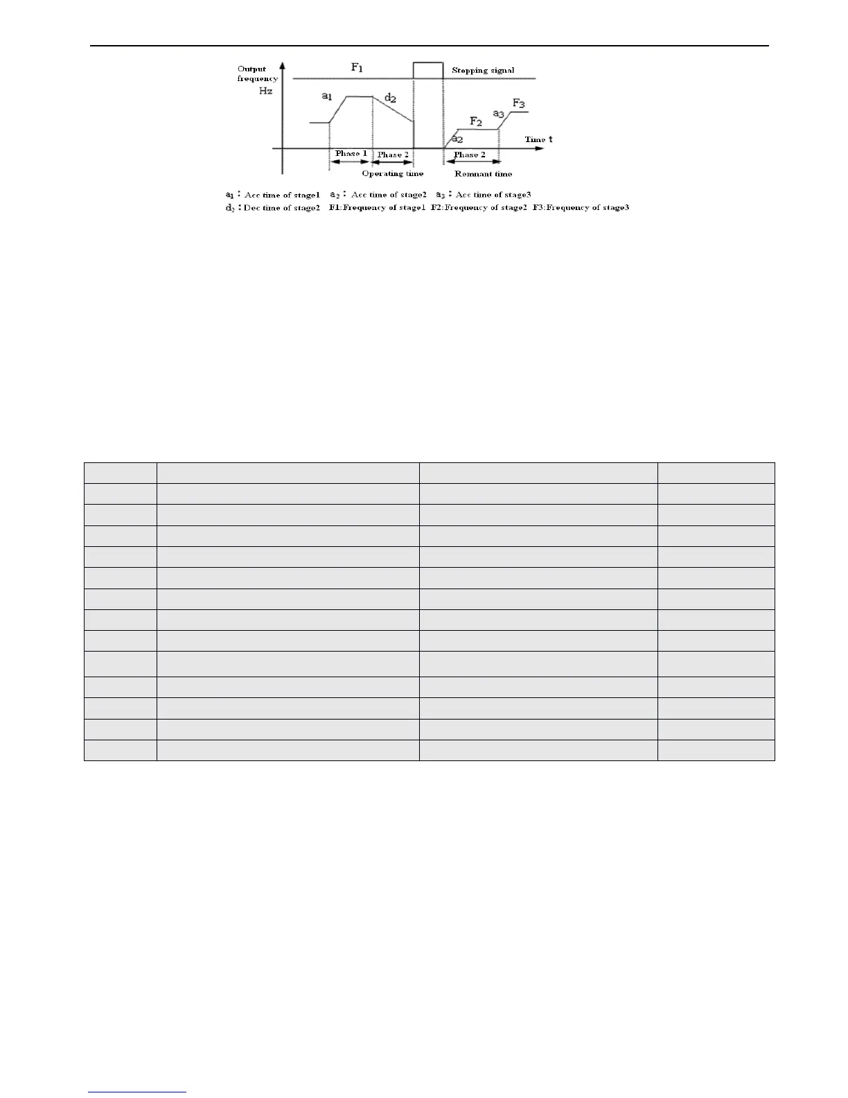
saving. The inverter does not save the PLC operating status after power off and re start to operat e in first stage .
1
1
1
1
:
Save.
Save.
Save.
Save. Save the operating parameters of PLC operation after power off
,
including the operating stage, operating frequenc
y
and operating time. The inverter will continue to operate in the mode defined
by
the ten
’
s place.
Thousand
Thousand
Thousand
Thousand
’
’
’
’
s
s
s
s place
place
place
place of
of
of
of LED
LED
LED
LED : PLC running time
0
0
0
0 : second
second
second
second
1
1
1
1 : minute
minute
minute
minute
This unit only valid for the definition of PLC running time. The unit of Acc/Dec time durning PLC is running is set
by
P0.16 .
Note
Note
Note
Note : (1) This stage is invalid when the PLC running time is set as 0.
(2)
You
can control pause, invalidation, run and others for the PLC process via terminals, refer to group P4 for details.
F requency setup
0 : Multi i ( i = 1 ~ 7 )
1: Frequency is decide
by
P0.01
Ten
’
s place of LED : Operating direction selection
0 : Run forward
1 : Run reverse
2 : Decided
by
operating instructions
Hundred
’
s place of LED : Acc/Dec time selection
With the unit
’
s place, ten
’
s place and hundred
’
s place of LED, P8.01~P8.14 defined the running frequency, direction and
Acc/Dec time of PLC :
Unit
Unit
Unit
Unit
’
’
’
’
s
s
s
s place
place
place
place of
of
of
of LE
LE
LE
LE D:
0
0
0
0 : Multi-frequency
Multi-frequency
Multi-frequency
Multi-frequency i
i
i
i
,
i=1~7
,
defined
by
P3.26~P3.32 .
1
1
1
1 : Frequency
Frequency
Frequency
Frequency is
is
is
is set
set
set
set by
by
by
by P0.01
P0.01
P0.01
P0.01
Ten
Ten
Ten
Ten
’
’
’
’
s
s
s
s place
place
place
place of
of
of
of LED
LED
LED
LED : Operating direction selection
 Loading...