VB5N series inverter
12
shown in Fig2-3.
In order to make the input over-current protection and power off maintenance easily, the inverters should connect
power supply via braker.
The connection cable of relay I/O circuit (X1~X4, X6, FWD, REV, OC, DO) should select the twisted-pair or shield
cable with diameter over 0.75 mm². One terminal of the shield layer should be hung in the air and the other terminal
should be connected with the inverter’s grounding terminal PE, the cable length should be less than 50m.
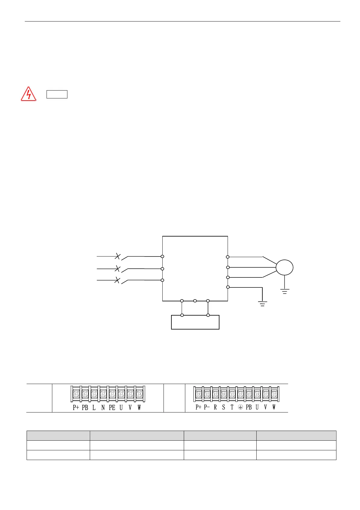
2-3. Wiring of main circuit terminals
2-3-1. Wiring diagram
Fig. 2-3 Wiring of main circuit
2-3-2. Terminal assignment and description
The relationship between main circuit terminals and product types:
Before layout operation, make sure the power supply of inverter is cut off, all the LED on the operate panel is black out
and delay for more than 10 minutes.
Wiring work can be performed after the voltage between internal electrolesis capacity “+” and “–” is below DC36V.
Wiring work can only be done by trained and professional personnel.
Before power on, please check if the power supply voltage is consistent with the inverter voltage level, otherwise
device damage, human injuries and deaths may occur.

 Loading...