VB5N series inverter
17
power supply common
terminal
Reference ground of analog signal and
+10V power supply
COM is isolated with GND inside
inverter
+24V power supply
common terminal
Digital signal I/O common terminal
This function is not open for user
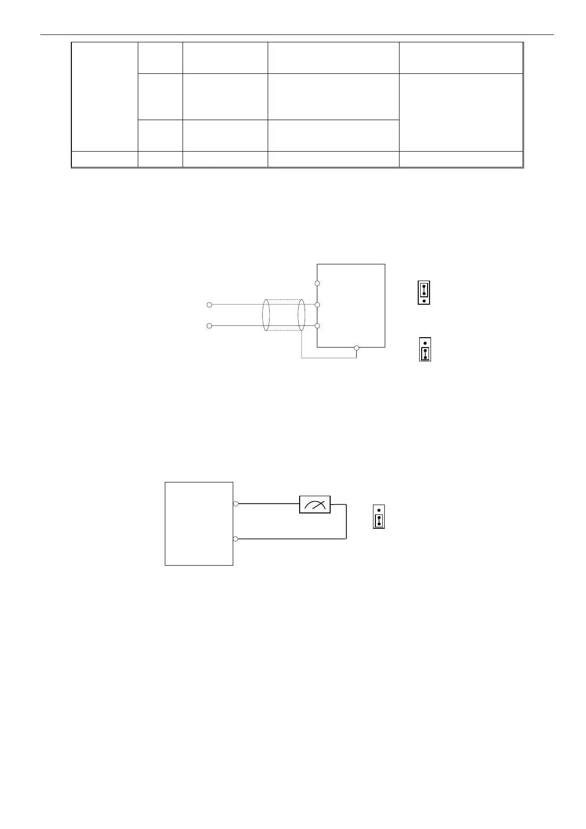
2-5-3. Analog I/O terminal wiring
1. CI terminal analog input, jumper select voltage input (0~10V) or current input (4~20mA):
Fig. 2-6 CI terminal wiring
2. Wiring for analog ouput terminal AO
Analog output terminal AO can display various physical quantities. The output voltage is 0~10V, output current is
4~20mA.
Fig. 2-7 Analog output wiring
Note:
(1) When using analog input, you can connect filter capacitor or common mode choke between CI and GND.
(2) Because analog input signal is easily interfered by outside, the shield cable is required, the cable length must be short
and the shield layer must be grounded well.
(3) The resistor connecting between control terminal 10V and GND is 5~10K.
2-5-4. Connection of communication terminals
The communication port of this inverter is standard RS485 port.
With the following wiring methods, you can build up control system of one-master-one-slave or one-master-multi-slaves.
Also, the superior device (PC or PLC) can realize the functions such as real time monitor inverter, remote control, highly
automated motion control.
Ground the proximal
Point of shield cable

 Loading...