EasyManuals Logo

Xinje VB5N Series User Manual

Xinje VB5N Series
105 pages
To Next Page IconTo Next Page
To Previous Page IconTo Previous Page
Page #26 background imageLoading...
Page #26 background image
VB5N series inverter
18
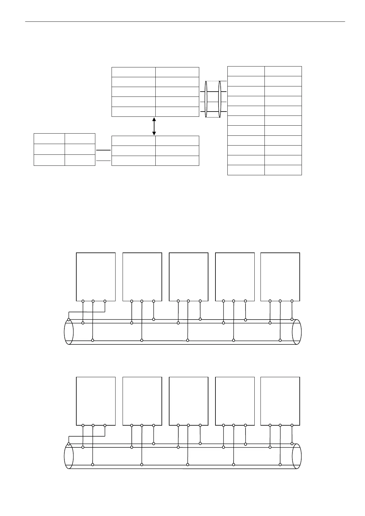
Connection of inverter RS485 port and superior device:
Fig. 2-8 RS485-(RS485/232)-RS232 cable connection
Many inverters can be connected together through RS485, the PLC(or PC) is the master device, as shown in Fig.2-9;
Also, you can select one inveter as master and the other inverters are slaves, as shown in Fig.2-10.The more inverters
are connected, the communication system will be interfered seriously, the following wiring is recommended.
Fig. 2-9 Connection of PLC and inverters
(Inverters and motors are all grounded well)
Fig. 2-10 Connection of several inverters
(Inverters and motors are all grounded well)
Inverter
master
Inverter
Inverter
Inverter
Inverter
A B PE
A B PE
A B PE
A B PE
A B PE
PLC
Master
Inverter
Inverter
Inverter
Inverter
A B PE
A B PE
A B PE
A B PE
A B PE
Shield
cable
Frequency inverter
Inverter
RS485/RS232 converter
Terminal
Name
5V power +
+5V
Send data
TXD
Receive data
RXD
5V power -
GND
Terminal
Name
A
Signal -
B
Signal +
Terminal
Name
Signal -
A
Signal +
B
Superior device
RS232 (DB9)
Signal
Pin
PE
Cover
RXD
2
TXD
3
GND
5
DTR
4
DSR
6
RI
9
CD
1
RTS
7
CTS
8

Table of Contents

Questions and Answers:

Question and Answer IconNeed help?

Do you have a question about the Xinje VB5N Series and is the answer not in the manual?

Xinje VB5N Series Specifications

General IconGeneral
BrandXinje
ModelVB5N Series
CategoryInverter
LanguageEnglish

Related product manuals