VB5N series inverter
16
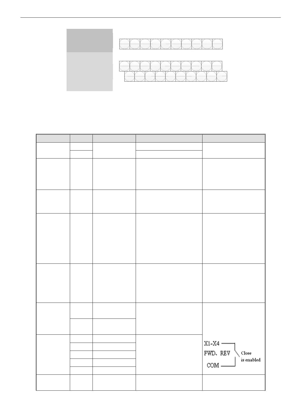
2. Control circuit terminal J3 (VB5N-S has the same terminals of VB5N, but some terminals don’t have real functions):
A B X1
X2
X3 FWD REV COM
10V
CI
485+ X1 X3 FWD REV AO
10V
485- X2 X4
X6
COM 24V CI GND
PEOC
Fig. 2-5 Terminals on control panel
3. CN2 terminals’ function description are shown as below:
Table 2-4 CN2 terminals’ function description
Terminal Function Description
RS485 differential signal +
standard RS485 port, please use
twisted cable or shielded cable
RS485 differential signal -
Multifunction
output terminal
Open collector output
terminal 1
Multi-function digital output terminal,
refer to P4.10 for details (common
terminals: COM)
optical coupling isolation output
voltage range: 9~30V
max output current: 50mA
please refer to P4.10 for details
Open collector pulse
output terminal
Multi-functional pulse output termi-
nal, refer to P4.20, P4.21 for details
(common terminals: COM)
Output frequency range: set
P4.21, the max is 20KHz
Analog current/voltage input, volt-
age and current are selected by
jumper JP3 and the default is cur-
rent. (reference ground: GND)
Input voltage range: 0~10V
(input resistance: 47KΩ)
Input current range: 4~20mA
(input resistance: 500Ω)
Resolution: 1/1000
Analog voltage/current ouput, they
are selected by jumper JP2 and the
default is voltage which can indi-
cate 7 values. (reference ground:
GND)
Voltage output range: 0~10V
Current output range: 4~20mA
Forware/reverse digital command.
Refer to P4.08 for details (instruc-
tion about 2-wire and 3-wire con-
trol function).
Optical coupling isolation input
Input resistance: R=2KΩ
Highest input frequency: 200Hz
Input voltage range: 9~30V
Multifunction
input terminal
Multi-function digital input termi-
nals, refer to parameter P4.
 Loading...