VB5N series inverter
48
Fig. 4-2 Characteristic parameter
FH(highest frequency), FL(lowest frequency) are defined by P0.19 and P0.20 .
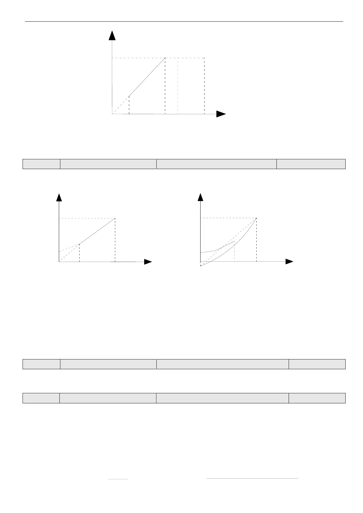
Improve inverter low frequency torque characteristics, boost-compensate the output voltage.
(a) Constant torque curve (b) square torque curve
Fig. 4—3 Torque boost
Cutoff frequency of torque boost
Range: 0.00Hz~Basic running frequency
This function defines the cut-off frequency of torque boost, as shown in Fig. 4-3 Fz. Then cut-off frequency is suitable for
any V/F curve defined by P0.02.
0: Manual torque boost
Torque boost voltage is defined by parameter P0.09. The boost voltage is fixed while motor will be easily magnetism satu-
ration with light load.
1: Auto torque boost
Torque boost voltage will change with the motor stator’s current. The bigger the stator current is, the higher the boost
voltage.
2×rated current of inverter
Vb: manual torque boost voltage
Vmax: max output voltage
Fz: cut-off frequency of torque boost
FB: basic running frequency
Vb: manual torque boost voltage
Vmax: max output voltage
Fz: cut-off frequency of torque boost
FB: basic running frequency
Output current of inverter
 Loading...