VB5N series inverter
58
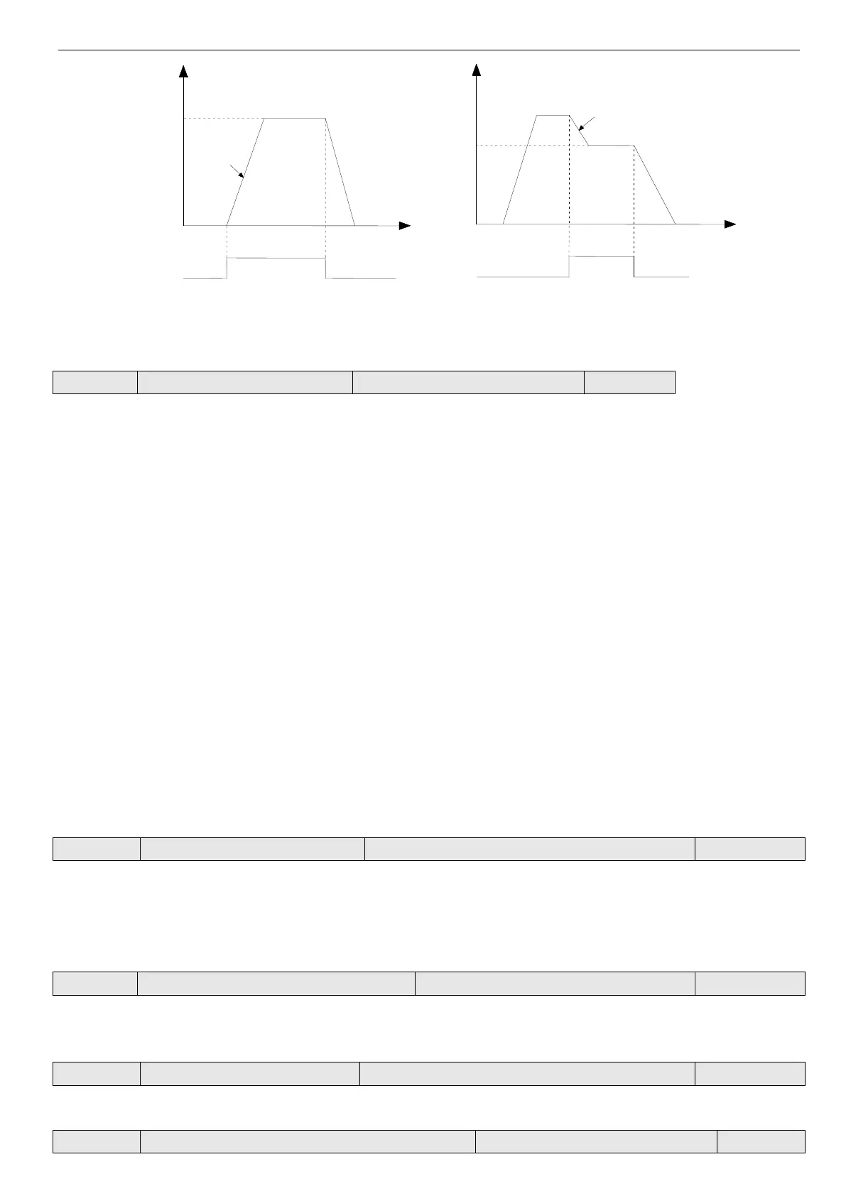
Fig 4-14 Jog operation
Note: (1) Jog operation can be controlled by panel, terminal and serial port.
(2) If jog operation command has been canceled, the inverter will decelerate and stop.
Communication configuration
You can change baud rate, digital format and communication mode by setting the lowest bit, ten bit, and hundred bit of
P3.09.
Lowest bit of LED: Set baud rate, the values are shown below:
0: 1200BPS
1: 2400BPS
2: 4800BPS
3: 9600BPS
4: 19200BPS
5: 38400BPS
Ten bit of LED: Set digital format, the values are show below:
0: 1-7-2 format, no parity check; 1 stop bit, 7 data bits, 2 stop bits, no parity.
1: 1-7-1 format, odd; 1 stop bit, 7 data bits, 1 stop bits, odd
2: 1-7-1 format, even; 1 stop bit, 7 data bits, 1 stop bit, even
3: 1-8-2 format, no parity check; 1 stop bit, 8 data bits, 2 stop bits, no parity.
4: 1-8-1 format, odd;1 stop bit, 8 data bits, 1 stop bit, odd
5: 1-8-1 format, even;1 stop bit, 8 data bits, 1 stop bit, even
6: 1-8-1 format, no parity check; 1 stop bit, 8 data bits, 1 stop bit, no parity.
Hundred bit of LED: undefined
Note: when choose Modbus-RTU communication mode, you should select digital format 3~6.
This parameter is used to identify the inverter’s address in serial communication.
0 is the broadcast address. If inverter is a slave, it doesn’t have to answer the 0 command.
248 is inverter master address. If set P3.10 to 248, it can send broadcast command to other inverters to realize mul-
ti-machine working. This function is in developing.
Communicate overtime checking time
When serial port communication failed and the lasting time is over this parameter, the inverter is considered as communi-
cation error.
When set the value to 0, the inverter will not detect the serial communication port and this function is disabled.
It refers to time from inverter’s serial port receiving and executing the command of host PC to returning response to it.
Proportion of communication frequency
 Loading...