VB5N series inverter
66
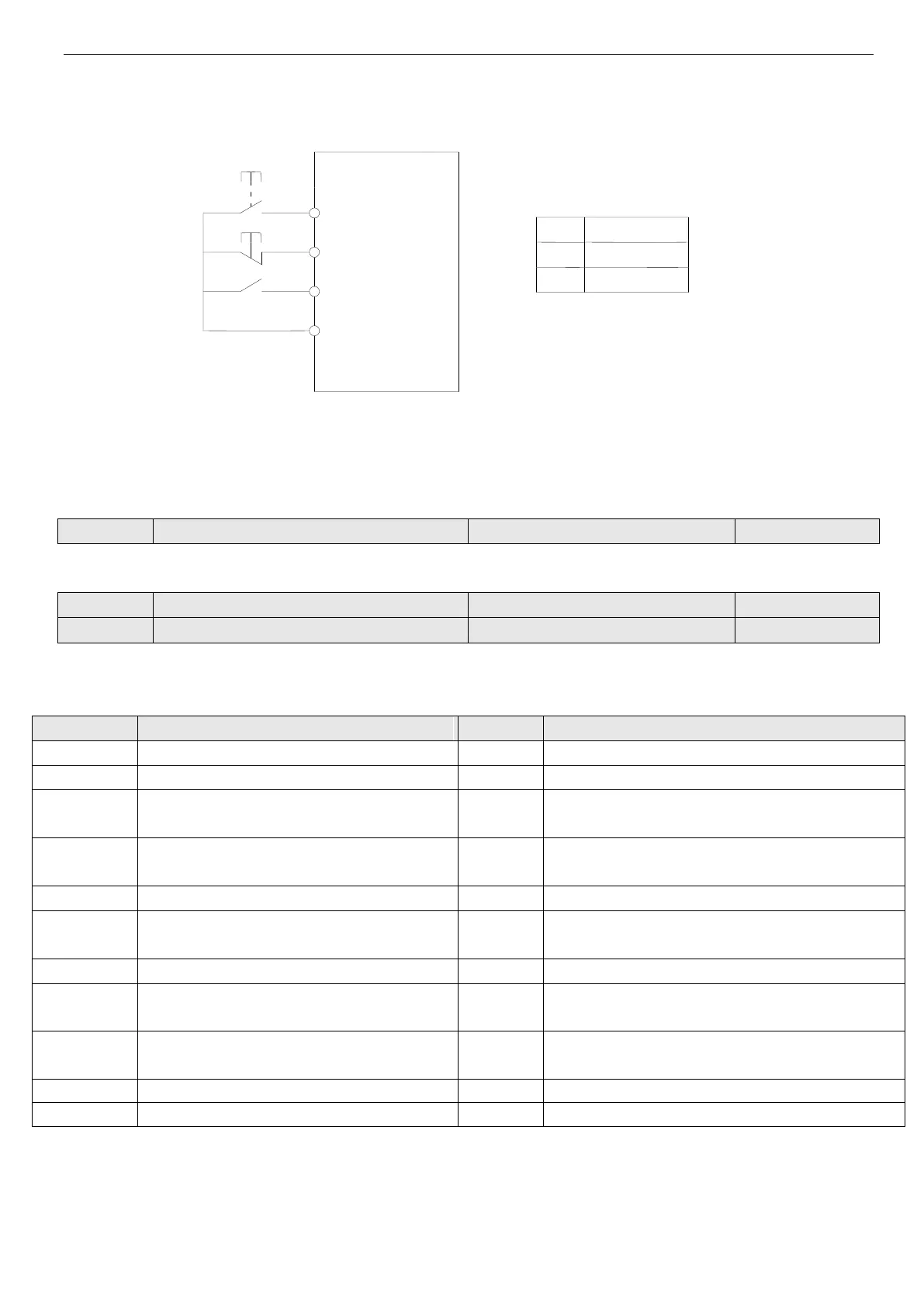
3: 3-wire control mode 2
SB1: Stop button
SB2: Running button
Fig.4-24 3-wire control mode 2
Xi is the multi-function input terminal of X1~X6, here you should define its function to No.9 “3-wire control mode”.
Note: When the inverter alarming stop, if the running command channel is terminal and terminal FWD/REV is valid, in-
verter will reset the error and restart immediately.
This parameter defines the changing rate of setting frequency changed by UP/DOWN terminal.
Bi-direction open-collector output terminal OC
Relay output function selection
Bi-direction open-collector output terminal OC, the options of this parameter are shown in Table 4-6.
Table 4-6 Functions of output terminals
Inverter is running (RUN)
PLC one period running is completed
Frequency arriving signal (FAR)
Reach the setting counter value
Frequency level detection signal (FDT1)
Reach the middle counter value
Frequency level detection signal (FDT2)
Inverter running preparation finished (RDY)
Inverter under voltage locking (LU)
Running at start frequency
External fault stop (EXT)
Upper limit of output frequency (FH)
Lower limit of output frequency (FL)
High and lower limit of swing frequency
Inverter zero speed running
Reach the preset running time
Simple PLC running completed
Instructions of the functions shown in Tabel 4-6:
0: Inverter is running(RUN). Inverter is running and the terminal outputs indication signal.
1: Frequency arriving signal (FAR). Refer to P4.12.
2: Frequency level detection(FDT1). Refer to P4.11~ P4.12.
3: Frequency level detection(FDT2). Refer to P4.13~P4.14.
 Loading...