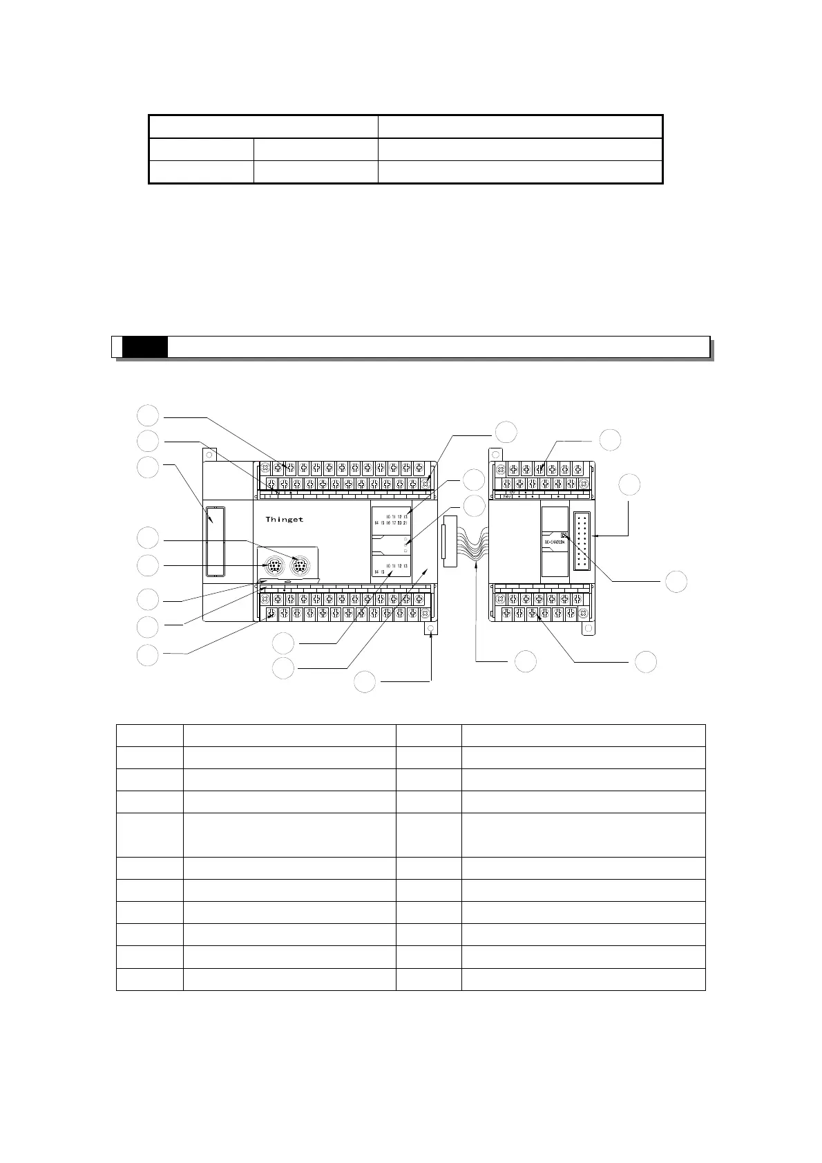
1-3.Each Part's Description
FG
COM
COM
X0
X1
X2
X3
X4
X5
X6
X7 X15
X16X14
X13
X12
X11
X10
X17
X20
X21
PWR
Y
X
PORT1 PORT2
Y15
Y14
Y13
Y12COM3
Y5
Y7
Y6
Y11
COM4
Y10
Y4
Y3COM2
Y2
COM1
Y1
COM0
Y0
A
B
24V
0V
10 4 532
RUN
ERR
XC3-32R-E
67
76
23 5401
AO1
AO0
VO0
VO1
C1
C0
VI3
AI3
C0
VI0 AI1
AI0
VI1 C2
AI2
C3
VI2C1
PWR
AI
AO
2
3
4
5
6
7
8
9
10
11
12
13
14
15
16
17
19
18
Each part's name is listed below:
Number
Name Number
Name
1 Input&power supply terminals 11 Installation holes (2)
2 Input terminal label 12 Screws to install/remove the terminals
3 Port to install BD card 13 Input LED
4 COM2 14 Action LED: PWR (power); RUN
(RUN); ERR (Error)
5 COM1 15 Expansion cable
6 Cover plate for COM port 16 Output terminals
7 Output terminal label 17 Action LED: PWR (power);
8 Output& 24V power terminals 18 Port to connect with expansion
9 Output LED 19 Input&power supply terminals
10 Port to connect with expansion
Model Description
Temperature
XC-2AD2PT-BD 2CH analogue input, 2CH PT100 temperature testing
Communication
XC-COM-BD RS-485/232 communication
CPU Unit Expansion
 Loading...