VESDA VLI Product Guide VESDA by Xtralis
26 www.xtralis.com
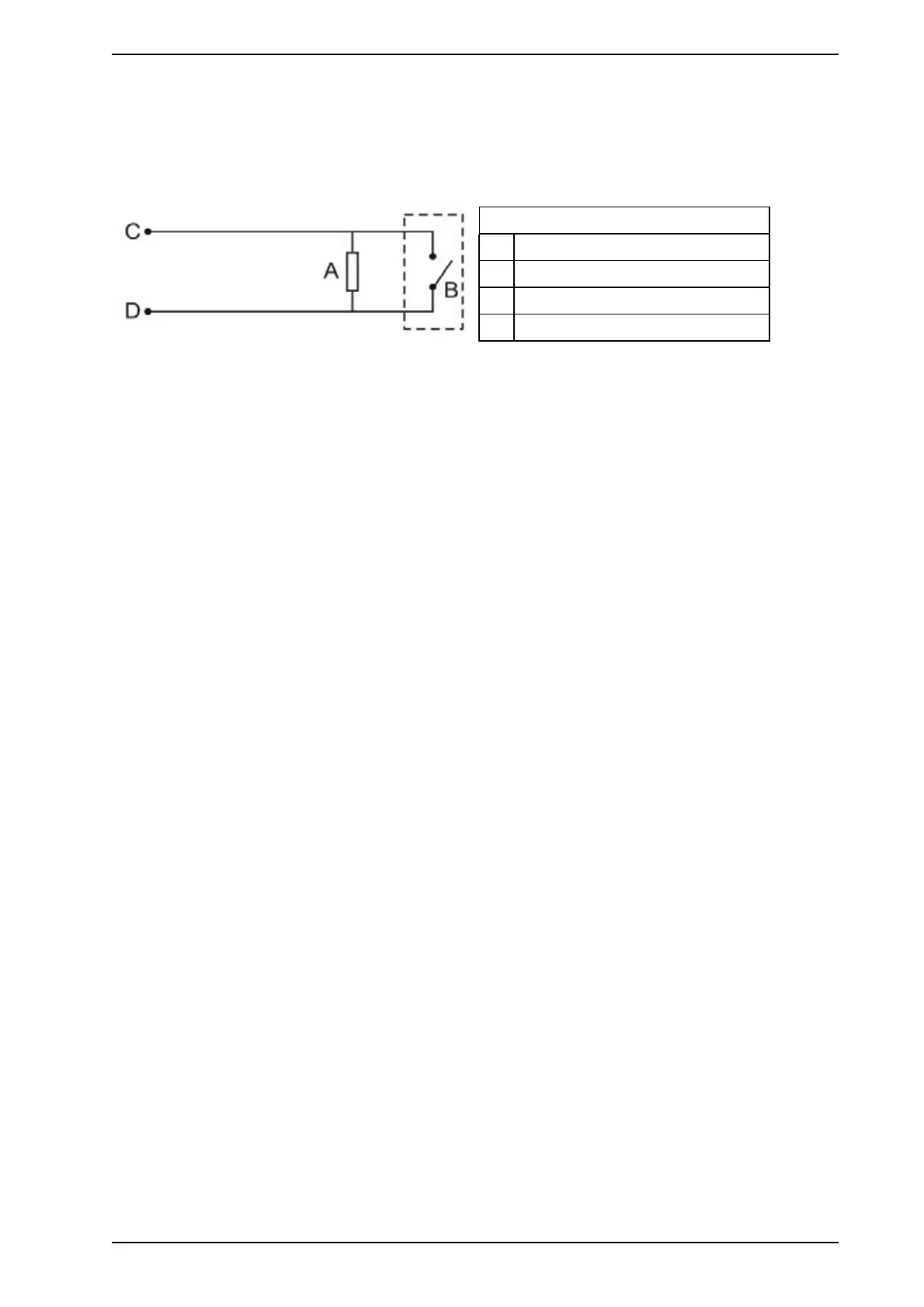
3.2.10 Typical Wiring for Monitored GPI for PSU Monitoring
(VLI-885only)
The diagram below shows the correct way to configure power supply monitoring with a VLI-885 detector. It
also shows where an End Of Line (EOL) resistor is correctly installed.
Legend
A End of Line Resistor (2.7k)
B External device (1 to N)
C GPI Pin 1
D GPI Pin 2
Figure 3-15: Power Supply Connection Diagram