VESDA by Xtralis
VESDA Accessories Guide
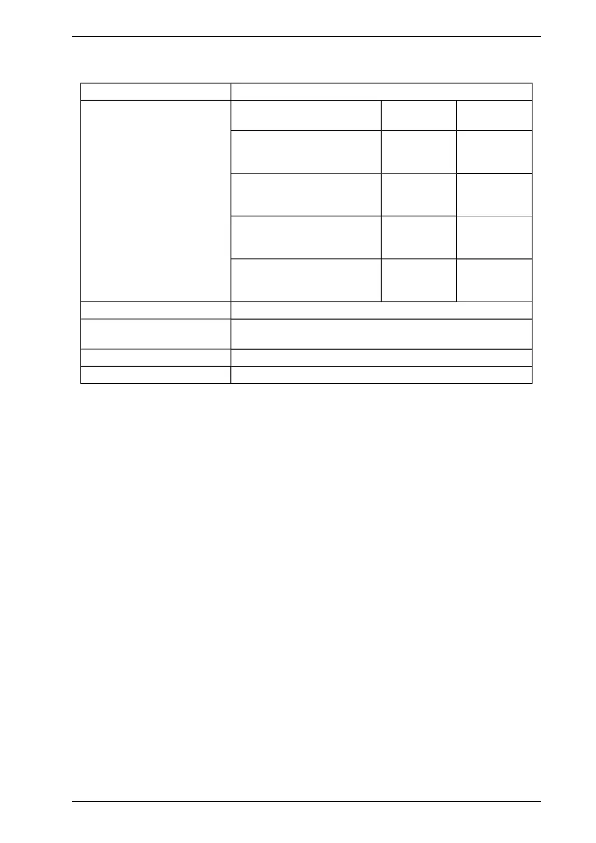
4.4.3 Remote Termination Card Module Specifications
Supply Voltage 18 to 30 VDC
Power Consumption Power Consumption (W) @24
VDC
Silent With Alarm
Remote Termination Card 7
Relay and relay processor card -
Power
1.44 W 2.52 W
Remote Termination Card 7
Relay and relay processor card -
Current
60 mA 105 mA
Remote Termination Card 12
Relay and relay processor card -
Power
Remote Termination Card 12
Relay and relay processor card -
Current
Dimensions (WHD) 105 mm (4.1 in.) x 130 mm (5.3 in.) x 26 mm (1.02 in.)
Dimensions in Remote Mounting
Unit
140 mm (5.5 in.) x 150 mm (5.9 in.) x 85 mm (3.4 in.)
Operating Temp. 0° to 39°C (32° F to 103° F)
Humidity 10-99%RH non-condensing
4.4.4 Mounting the Remote Termination Card
The remote termination card module is easily mounted onto a remote box and the 19” Subrack. For details on
mounting refer to Mounting a Remote Box on page 8 and Mounting a 19” Subrack on page 10.
4.4.5 Wiring the Remote Termination Card Module
The relay processor card is connected to a 7 or 12 relay remote termination card. For details on wiring the
remote termination card and relay processor Module please refer to Wiring Remote Systems on page 11.
www.acornfiresecurity.com
www.acornfiresecurity.com