Installation/Mounting
1: Select pump location. Pump must be installed in a dry, ventilated
area.
CAUTION: Installation Notes: To avoid the risk of re. Be sure that
the area where pump is installed is isolated from gas, fuel tanks,
electrical wiring looms or ammable substances. Failure to do so
may cause injury or death.
Figure 2.
Figure 1.
Figure 4.
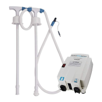
Pumpgard
Strainer
To discharge
point
Figure 3.
Inlet Strainer (A)
Discharge (B)
Horizontal Vertical NOTE: Do Not Submerge
CAUTION: Not For Continuous Duty, Intermittent Duty Only
CAUTION: Installation Notes: To avoid the risk of re. Do not install
this product if visible damaged. If damage exposes electrical
contacts, electrical sparks could ignite fuel fumes. Failure to do so
may cause injury or death.
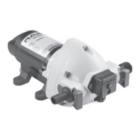
2: Connect ttings supplied
with the pump to the system
plumbing. Use ½” (13mm)
I.D. exible hose (preferably
braided or reinforced) to
reduce vibration through the
plumbing system (Figure 1).
Use hose clamps on the slip on
barb hose connectors.
Important: Install strainer in the
pump inlet to protect valves
from debris.
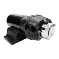
3: Fasten pump to a at surface. If
mounting vertically; install with
pumphead down (Figure 2)
Do not over tighten screws to
allow rubber mounts to absorb
vibration.
4: Install inlet (A) and discharge
(B) ttings. Firmly push slide
clips (C) forward to lock ttings
in place. – Figure 3
4
 Loading...