38
Control terminals
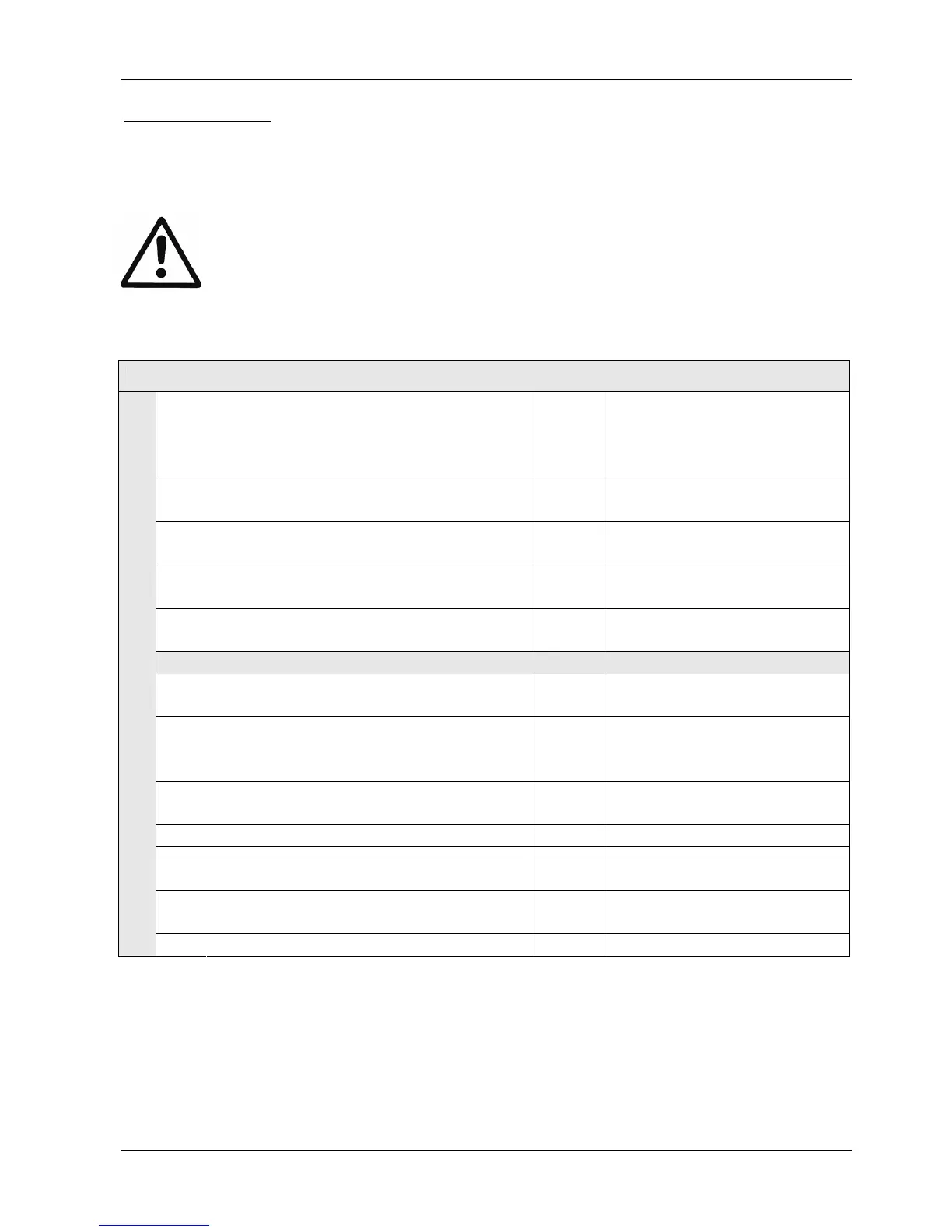
All control cables connected to the control card have to be screened (See chapter 9.3
recommended cable types).
External volt free contacts must be suitable for switching <10 VDC.
NOTE: If unscreened control cables are used, signal interference may occur
and could also interfere incoming signals and the function of the
HYDROVAR.
Do not connect the ground of the control card to other voltage potentials.
All electronic ground terminals and GND of the RS 485-interface are connected internally.
X3 Digital and Analogue I/O
1
GND, electronic ground
2
Actual value current input sensor 1
0-20mA / 4-20mA [Ri=50Ω]
3
Power supply for external sensors
24VDC, ** max. 100mA
4
Actual value current input sensor 2
0-20mA / 4-20mA [Ri=50Ω]
5
Actual value voltage input sensor 2
*Dig 3 0-10 VDC
6
Actual value voltage input sensor 1
*Dig 2 0-10 VDC
7
External ON/OFF (release)
Active low
8
GND, electronic ground
9
Configurable digital input 1
Dig 1 Active low
10
GND, electronic ground
11
Low water
Active low
12
GND, electronic ground
13
Voltage signal input (required value 1)
(Offset)
24
+24V power supply for control inputs
24VDC, ** max. 100mA
* Terminals 5 and 6 can be used as actual value voltage input and also as digital input.
Also the voltage signal input on terminal X3/15 can be used as digital input.
** X3/3 and X3/24 Æ ∑ max. 100mA
(Offset) These terminals can be used as required value or offset signal input.
Configuration: see submenu REQUIRED VALUES [0800] and submenu OFFSET [0900].
 Loading...


