8
2 System design
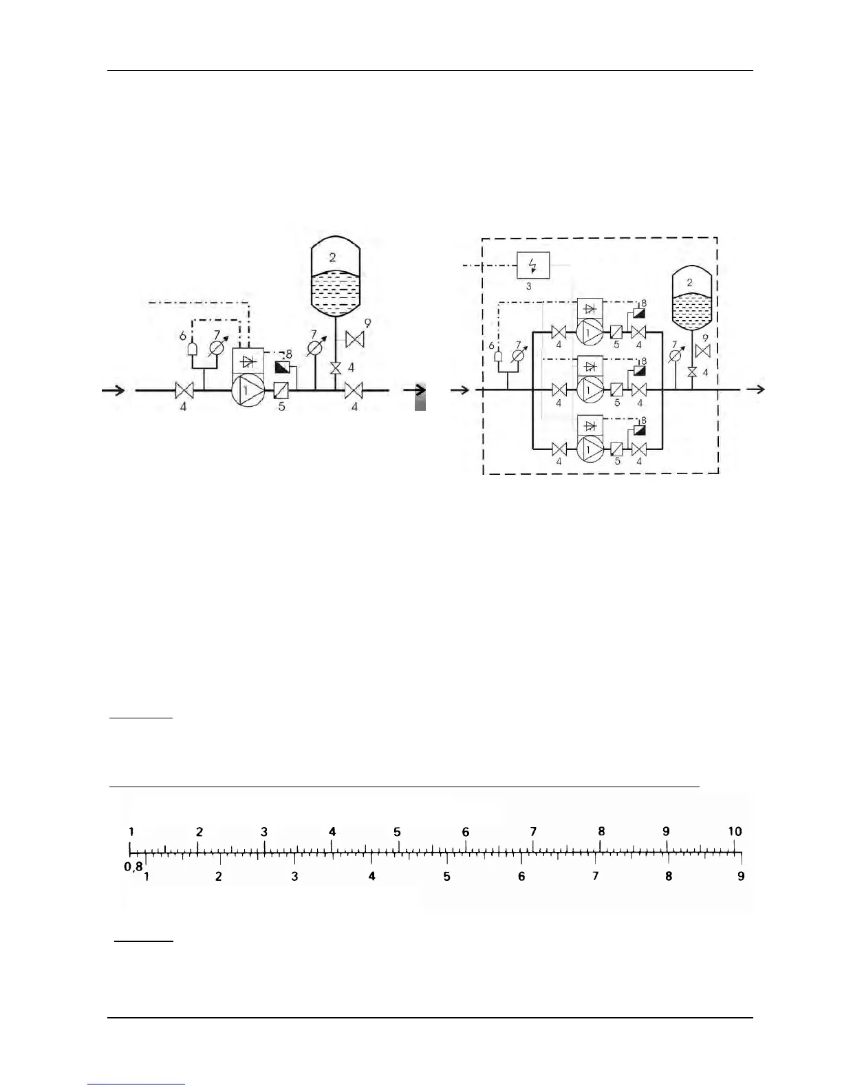
The following diagrams show typical SINGLE and multi-pump systems using the
HYDROVAR. Connection can be made directly to a water supply. In such a case, the use of a
low pressure switch on the suction is recommended.
SINGLE pump layout Multi pump layout
(1) pump with HYDROVAR
(2) diaphragm tank
(3) distribution panel
(4) gate valve
(5) non return valve
(6) low water control
(7) pressure gauge
(8) pressure transmitter
(9) drain tap
2.1 Pressure tank
A diaphragm pressure tank is used on the discharge side of the pump to maintain pressure
in the line when there is no water demand. This avoids the pump from continuing to run at
zero demand. With the HYDROVAR, no large tanks are required for supply purposes.
The tank must be permitted and suitable for systems pressure. The tank should have a
capacity of min. 10% of the maximum system flow rate [l/min] of one pump (also valid for
multi-pump system).
Example:
Maximum flow rate of the pump = 250 litres per minute
Minimum volume of the tank = 250 x 0.10 = 25 litres
The pre-charge pressure of the tank can be determined by using the following table:
NOTICE:
To check and set the right pre-charge pressure, please reduce the water
pressure to zero by turning the HYDROVAR off.
required pressure [bar]
pre-charge pressure [bar]
 Loading...


