5-15
Outboard Rigging Guide - 2001 Trim Meter
Trim Meter Sender Adjustment
Checking
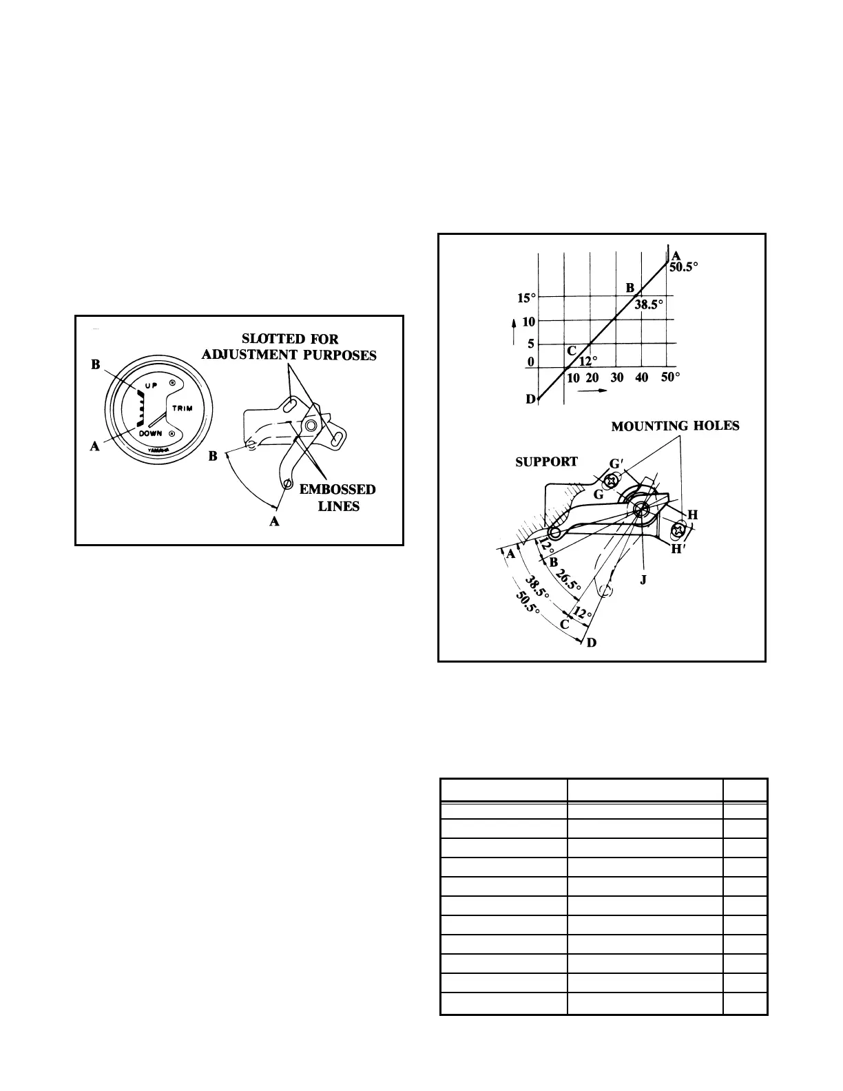
1. When checking the trim sender, connect the
lead wires of the trim sender and move the
lever up and down. The trim sender needle
should point to the “UP” position when the
level is set to “B” and the “DOWN” position
when set to “A.”
2. The trim sender lever position (angle) and the
trim meter needle relate as shown in the pre-
vious illustration. They should be adjusted so
the needle aligns with the marking line indi-
cating “DOWN.” If this adjustment is made
with the needle below the line, the engine
cannot be trimmed up as required.
NOTE: Install the trim meter so it tilts 50° to 80°.
Also, avoid placing any strong magnet or magne-
tized object near the trim sender.
Adjusting
1. For a down position adjustment, loosen the
trim sender screws and make an adjustment
so the needle aligns with the marking line
indicating “DOWN.”
NOTE: To adjust the trim sender bracket posi-
tion, loosen the bolts and turn the bracket on pivot
“J” and tighten the bolts. The bolt positions will
be changed from G to G' and from H to H'.
Additional Parts Required
Part Number Description Qty
6R3-83672-01-00 Trim Sender 1
97885-06016-00 Pan Head Screw 1
6Y5-83553-00-00 Lead Wire 1
1E6-82151-00-00 Fuse (10A) 1
6R3-82553-10-00 Wire Lead Extension 1
6R3-82553-30-00 Wire Lead Extension 1
6R3-82553-57-00 Wire Lead Extension 1
6R3-82553-70-00 Wire Lead Extension 1
6R3-82553-80-00 Wire Lead Extension 1
6R3-82553-90-00 Wire Lead Extension 1
90465-11M10-00 Clamp 3
 Loading...