Do you have a question about the Yamaha A-960 and is the answer not in the manual?
| Weight | 12.5 kg |
|---|---|
| Frequency Response | 5Hz-100kHz (+0, -3dB) |
| Total Harmonic Distortion | 0.005% |
| Damping Factor | 80 |
| Input Sensitivity | 150mV (line) |
| Signal to Noise Ratio | 110dB (line) |
| Channel Separation | 70dB (1kHz) |
| Speaker Load Impedance | 4-16 ohms |
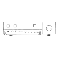
Overview of internal component layout from the top.
Instructions for removing the amplifier's top panel.
Instructions for removing the amplifier's bottom panel.
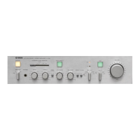
Steps to detach the front panel assembly from the unit.
Procedure for detaching the rear panel.
Steps to remove the function control circuit board.
Guide to separating the control section assembly.
Detailed steps for removing tone control circuit boards.
Procedure for removing main boards and heat sink.
Steps to detach control boards and power transformer.
Procedure to set the amplifier's idling current.
Steps to adjust the DC offset voltage.
Procedure for checking and adjusting B power line voltages.
Test procedure for the photocoupler voltage.
Adjusting tone control frequency response and filter settings.
Safety and handling precautions for control board adjustments.
Visual diagram showing component placement and part numbers.
Detailed list of mechanical parts with reference numbers.
Detailed list of electronic components on circuit boards.