19
DSP-A5
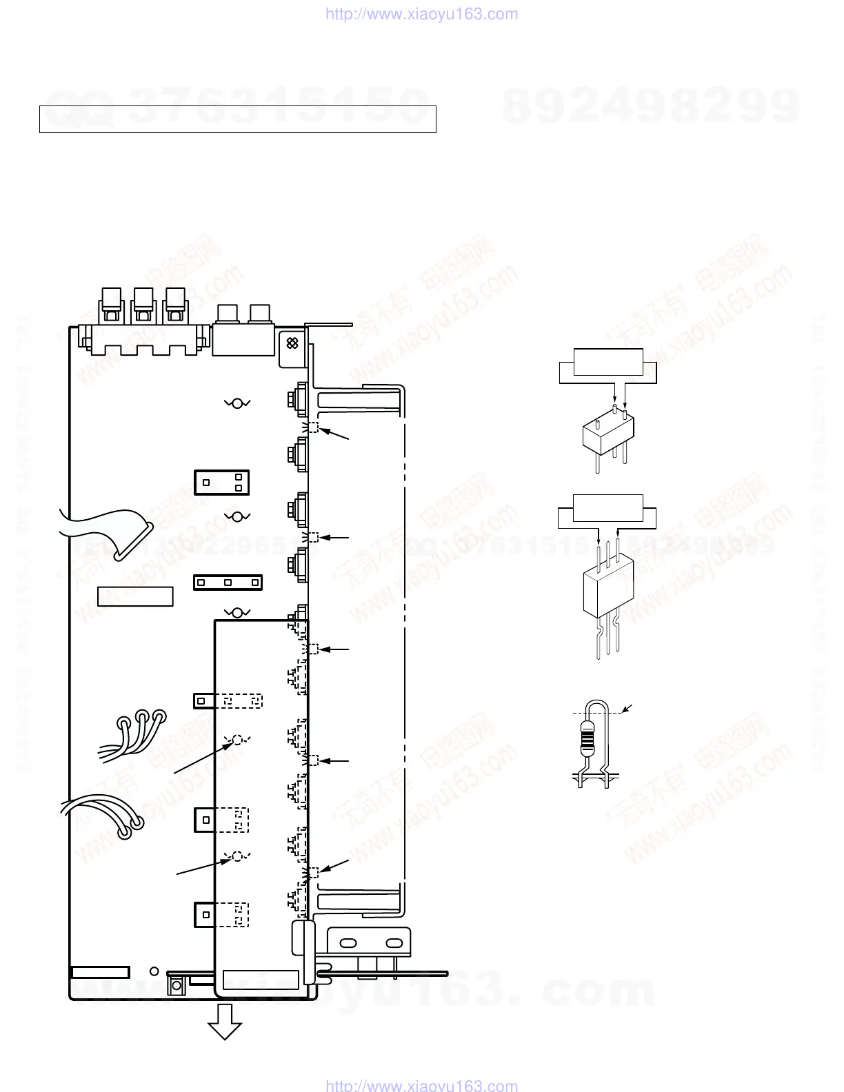
Confirmation of Idling Current of Main Amplifier
•
Right after power is turned on, confirm that the voltage across the
terminals of R688(Main Lch),R690(Main Rch), R692(Center),
R694(Rear Lch), R696(Rear Rch) are between 0.1mV and 10.0mV.
•
If it exceeds 10.0mV, open (cut off) R571 (Main Lch), R577 (Main
Rch), R583 (Center), R589 (Rear Lch), R595 (Rear Rch) and
reconfirm the voltage.
•
Confirm that the voltage is 0.20mV ~ 15.0mV after 60 minutes.
■ AMP ADJUSTMENT
Note)
•
If R571, R577, R583, R589 and
R595 have already been cut off
and idling current does not flow,
reconnect R571, R577, R583,
R589 and R595.
•
Q521 ~ Q525 are transistors for
temperature correction.
Apply silicone grease to contact
surface with the heat sink.
R571(Lch)
R577(Rch)
R583(Cch)
R589(RLch)
R595(RRch)
R583
R589
Q525
Q523
Q524
Q522
Q521
R692
R696
R595
MAIN (1)
Front Panel
R577
R571
0.1mV ~ 10.0mV
(DC)
R688(Lch)
R690(Rch)
R692(Cch)
R694(RLch)
R696(RRch)
Cut off
R694
R690
R688
POWER (3)
0.1mV ~ 10.0mV
(DC)
w
w
w
.
x
i
a
o
y
u
1
6
3
.
c
o
m
Q
Q
3
7
6
3
1
5
1
5
0
9
9
2
8
9
4
2
9
8
T
E
L
1
3
9
4
2
2
9
6
5
1
3
9
9
2
8
9
4
2
9
8
0
5
1
5
1
3
6
7
3
Q
Q
TEL 13942296513 QQ 376315150 892498299
TEL 13942296513 QQ 376315150 892498299
http://www.xiaoyu163.com
http://www.xiaoyu163.com
 Loading...