22
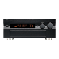
DSP-A5
IC107 : BU2090
Serial Input/Parallel Output Driver for Output port expansion
Pin Pin
Port I/O Function
No. Name
67
P05/FL21
P1 O Segment 1 for FL display
68
P04/FL20
P2 O Segment 2 for FL display
69
P03/FL19
P3 O Segment 3 for FL display
70
P02/FL18
P4 O Segment 4 for FL display
71
P01/FL17
P5 O Segment 5 for FL display
72
P00/FL16
P6 O Segment 6 for FL display
73
P57/FL15
P7 O Segment 7 for FL display
74
P56/FL14
P8 O Segment 8 for FL display
75
P55/FL13
P9 O Segment 9 for FL display
76
P54/FL12
P10 O Segment 10 for FL display
77
P53/FL11
P11 O Segment 11 for FL display
78
P52/FL10
P12 O Segment 12 for FL display
79
P51/FL09
P13 O Segment 13 for FL display
80
P50/FL08
P14 O Segment 14 for FL display
81
P67/FL07
P15 O Segment 15 for FL display
82
P66/FL06
P16 O Segment 16 for FL display
83
P65/FL05
P17 O Segment 17 for FL display
84
P64/FL04
P18 O Segment 18 for FL display
Pin Pin
Port I/O Function
No. Name
85
P63/FL03
P19 O Segment 19 for FL display
86
P62/FL02
P20 O Segment 20 for FL display
87
P61/FL01
P21 O Segment 21 for FL display
88
P60/FL00
P22 O Segment 22 for FL display
89
VEE
VP O Power supply for FL display
90
P107/AN7
LIMDT I Limitter DC detect input
91
P106/AN6
PRV I PS (power voltage) protection
AD value detect input
92
P105/AN5
PRD I DC (power amp voltage) protection
AD value detect input
93
P104/AN4
METER I Tuner meter AD value input
94
P103/AN3
NC O No connection
95
P102/AN2
/FMT O Full mute output (L: ON)
96
P101/AN1
KEY2 I Key 2 AD data value input
97 AVSS MG Ground
98
P100/AN0
KEY1 I Key 1 AD data value input
99 VREF +5M Standard power supply for AD input
100 AVCC +5BU +5V power supply
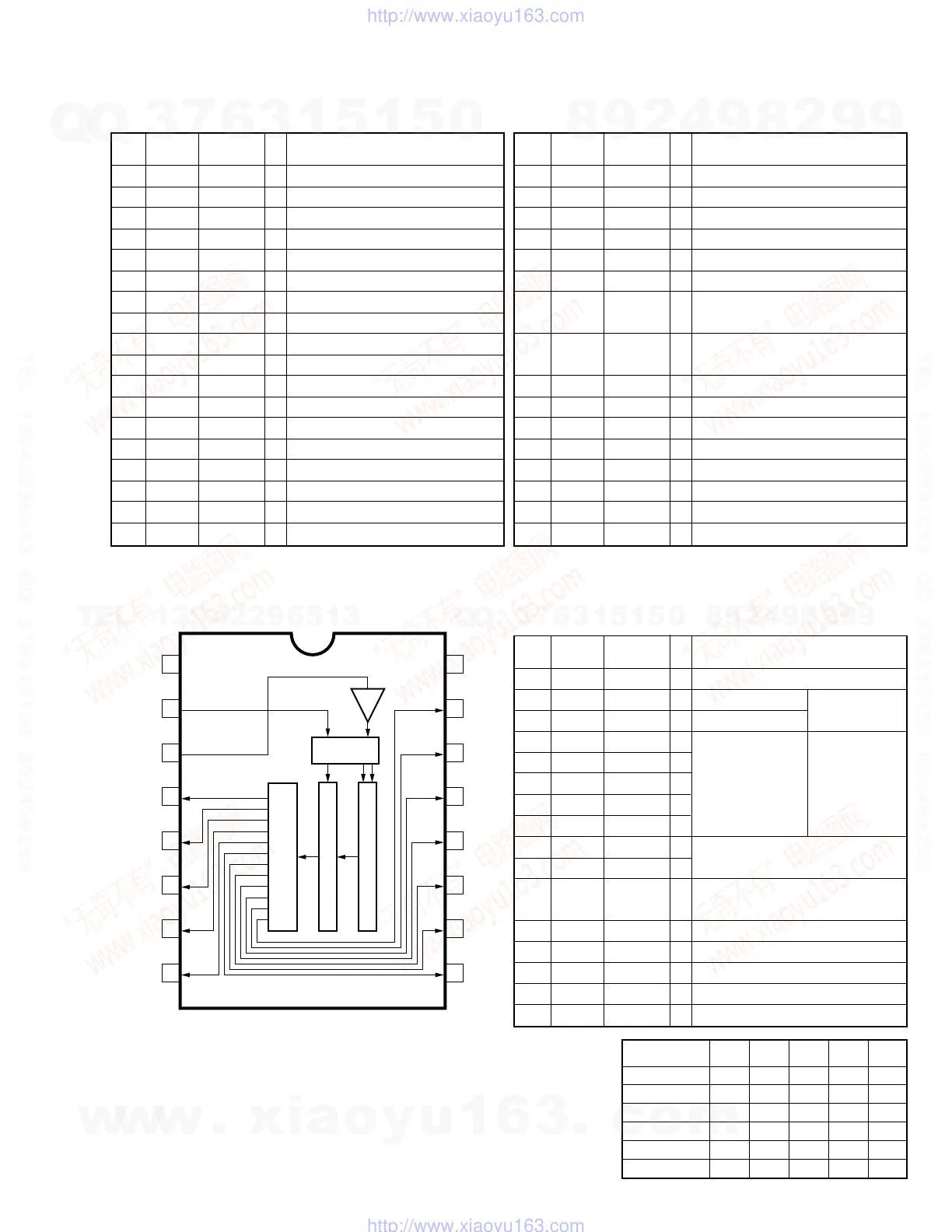
Pin Pin
Port I/O Function
No. Name
1 VSS VSS Ground
2 DATA DTB I Control data input
3 CLOCK CKB I Control clock input
4 Q0 SW1 O Video select data
5 Q1 SW2 O output 1-5(*)
6 Q2 SW3 O
7 Q3 SW4 O
8 Q4 SW5 O
9 Q5 /CONT1 O Limitter control data output 1,2
10 Q6 /CONT2 O
11 Q7 /-10dB O –10dB control data output
(L : –10dB)
12 Q8 /ICAC O Initial clear output for AC3D2av
13 Q9 NC O Unconnected
14 Q10 NC O Unconnected
15 Q11 /T-MUTE O Tuner mute data output (L : Mute on)
16 VDD VDD +5V power supply
2
1
3
4
5
6
7
8
15
16
14
12
12
11
10
9
VSS
DATA
CLOCK
Q0
Q1
Q2
Q3
Q4
VDD
Q11
Q10
Q9
Q8
Q7
Q6
Q5
OUTPUT BUFFER
(OPEN DRAIN)
LATCH
CONTROL
LOGIC
12-Bit SHIFT REGISTER
(TOP VIEW)
IC501 : M30217MA-A203FP
16-bit Microcomputer
from
microcomputer
for
video input
selector
* Video input
Selector
Control
(H=High,
L=Low,
X=Don't care)
Video Input SW1 SW2 SW3 SW4 SW5
(Pin4) (Pin5) (Pin6) (Pin7) (Pin8)
CBL/SAT H L X L H
D-TV H H X L H
DVD/LD H L L H H
VCR L H X X H
V-AUX H L H H H
OFF L L X X L
w
w
w
.
x
i
a
o
y
u
1
6
3
.
c
o
m
Q
Q
3
7
6
3
1
5
1
5
0
9
9
2
8
9
4
2
9
8
T
E
L
1
3
9
4
2
2
9
6
5
1
3
9
9
2
8
9
4
2
9
8
0
5
1
5
1
3
6
7
3
Q
Q
TEL 13942296513 QQ 376315150 892498299
TEL 13942296513 QQ 376315150 892498299
http://www.xiaoyu163.com
http://www.xiaoyu163.com
 Loading...