27
DSP-A5
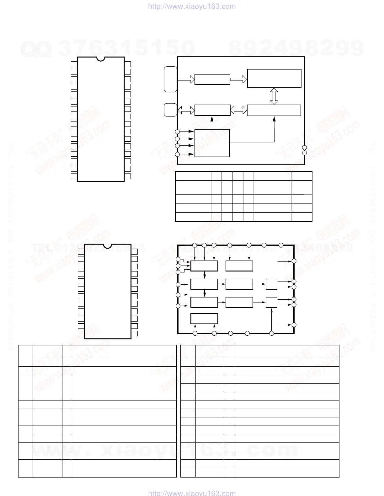
IC5 : IS61C1024-20J (1M SRAM)
131072-word x 8-bit High Speed Static RAM
NC
A3
A4
A5
A6
A7
A8
A9
A10
A11
A12
A13
D1
D2
D3
GND
1
2
3
4
5
6
7
8
9
10
11
12
13
14
15
16
VCC
A2
CE2
/WE
A1
A0
A16
A15
/OE
A14
/CE1
D8
D7
D6
D5
D4
32
31
30
29
28
27
26
25
24
23
22
21
20
19
18
17
DECODER
TOP VIEW
A0-A16
27,28
31,
2-12,
23,25
26
32
VCC
GND
16
/CE1
22
CE2
30
/WE
29
/OE
24
131072-word x 8-bit
MEMORY ARRAY
(512-row x 2048-column)
I/O DATA
CONTROL
COLUMN I/O
CONTROL
CIRCUIT
/CE1
H
X
L
L
L
/CE2
X
L
H
H
H
/OE
X
X
H
L
X
Mode Data I/O Power
NOTE) H: High Level L: Low level X: Don't care
NOTE)
A0-A16: Address input
D1-D8: Data input/output
/CE1,CE2: Chip enable input 1,2
/OE: Output enable input
/WE: Write enable input
Not Selected
(Power-down)
Output Disabled
Read
Write
High impedance
High impedance
High impedance
Output
Input
On
Standby
On
On
On
/WE
X
X
H
H
L
D1-D8
13-15,
17-21
IC7 : AK4324-VF-E2 (DAC)
1-bit D/A Converter
DVSS
DVDD
CKS
MCLK
/PD
BICK
SDATA
LRCK
SMUTE
DFS
DEM0
DEM1
1
2
3
4
5
6
7
8
9
10
11
12
13
14
15
17
DZFL
DZFR
AVDD
VREF
AVSS
AOUTL+
AOUTL-
AOUTR+
AOUTR-
DIF2
DIF1
DIF0
24
23
22
21
20
19
18
16
TOP VIEW
LRCK
8
BICK
6
SERIAL INPUT
INTERFACE
8x
INTERPOLATOR
∆∑
MODULATOR
SCF
SCF
∆∑
MODULATOR
8x
INTERPOLATOR
CLOCK
DIVIDER
/PD
5
AOUTL+
19
DZFL
24
AOUTL-
18
AOUTR+
17
AOUTR-
16
DZFR
23
SMUTE
9
DFS
10
MCLK
4
CKS
3
DVDD
2
DVSS
1
VREF
21
DIF0
13
DIF2
15
DIF1
14
DE-EMPHASIS
CONTROL
DEM0
11
DEM1
12
AVDD
22
AVSS
20
SDATA
7
Pin Pin
I/O Function
No. Name
1 DVSS Ground (digital)
2 DVDD Power supply (digital)
3 CKS I Master clock (MCLK) select input (Fixed L)
Normal speed (L:256fs, H:384fs)
High speed (L:128fs, H:192fs)
4 MCLK I 256fs bit clock input from DIR5
5 /PD I Power-down and reset, initial clear input from
AC3D2av (L:Reset)
6 BICK I 64fs bit clock input from DIR5
7 SDATA I Serial data input from AC3D2av
8 LRCK I 1fs word clock input from DIR5
9 SMUTE I Soft mute detect input (H:Soft mute, L:off)
10 DFS I Double speed sampling mode select input from
DIR5 (L:Normal speed, H:High speed)
Pin Pin
I/O Function
No. Name
11 DEM0 I
De-emphasis frequency select input 0 (Fixed H)
12 DEM1 I
De-emphasis frequency select input 1 (Fixed L)
13 DIF0 I Digital input format input 0 (Fixed L)
14 DIF1 I Digital input format input 1 (Fixed H)
15 DIF2 I Digital input format input 2 (Fixed L)
16 AOUTR- O Rch negative analog output
17 AOUTR+ O Rch positive analog output
18 AOUTL- O Lch negative analog output
19 AOUTL+ O Lch positive analog output
20 AVSS Ground (analog)
21 VREF I Reference voltage input
22 AVDD Power supply (analog)
23 DZFR O Rch zero input detect output
24 DZFL O Lch zero input detect output
w
w
w
.
x
i
a
o
y
u
1
6
3
.
c
o
m
Q
Q
3
7
6
3
1
5
1
5
0
9
9
2
8
9
4
2
9
8
T
E
L
1
3
9
4
2
2
9
6
5
1
3
9
9
2
8
9
4
2
9
8
0
5
1
5
1
3
6
7
3
Q
Q
TEL 13942296513 QQ 376315150 892498299
TEL 13942296513 QQ 376315150 892498299
http://www.xiaoyu163.com
http://www.xiaoyu163.com
 Loading...