RX-V2700/DSP-AX2700
13
RX-V2700/
DSP-AX2700
Fig. 3
Fig. 2
4. D-VIDEOP.C.B.の外し方
a.
0
のネジ2本を外し、シールドプレートを取り外しま
す。(Fig.2)
b.
A
のネジ1本、
B
のネジ2本を外します。(Fig.2)
c.
C
のネジ5本を外します。(Fig.5)
d. CB136、CB204、CB953、CB957を外します。(Fig.3)
e. D-VIDEOP.C.B.を取り外します。ただし、D-VIDEO
P.C.B.は、A-VIDEOP.C.B.と直接コネクター接続され
ています。(Fig.2)
5. A-VIDEOP.C.B.の外し方
a.
D
のネジ10本を外します。(Fig.5)
b. CB23、CB203を外します。(Fig.3)
c. A-VIDEOP.C.B.を取り外します。(Fig.2)
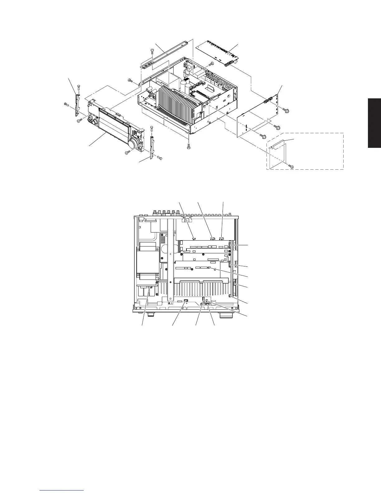
4. Removal of D-VIDEO P.C.B.
a. Remove 2 screws (0) and then remove the shield plate
(U, C, T, B, G, E models). (Fig. 2)
b. Remove 1 screw (A) and 2 (U, C, T, B, G, E models) / 3
(R, K, A, L models) screws (B). (Fig. 2)
c. Remove 5 screws (C). (Fig. 5)
d. Remove CB136, CB204, CB953 and CB957. (Fig. 3)
e. Remove the D-VIDEO P.C.B. which is connected di-
rectly to the A-VIDEO P.C.B. with connectors. (Fig. 2)
5. Removal of A-VIDEO P.C.B.
a. Remove 6 screws (D). (Fig. 5)
b. Remove CB23, CB203 and CB209. (Fig. 3)
c. Remove the A-VIDEO P.C.B.. (Fig. 2)
B
A
0
B
6
6
6
6
5
5
7
9
8
8
Side plate L
サイドプレートL
Frame top
フレーム/トップ
Side plate R
サイドプレートR
Shield plate
シールドプレート
Sub chassis unit
サブシャーシユニット
A-VIDEO P.C.B.
D-VIDEO P.C.B.
(U, C, T, B, G,
E, J models)
(R, K, A, L models)
CB806 CB814CB807CB12
CB957
CB23
CB953
CB136
CB805
CB970
CB971
CB203CB204CB209

 Loading...