RX-V2700/DSP-AX2700
16
6. Removal of Rear Unit
a. Remove 10 (U, C, T, A, B, G, E models) / 13 (R, L mod-
els) screws (E) and 4 (U, C, R, T, A, B, G, E, L models)
/ 2 (K model) screws (F). (Fig. 5)
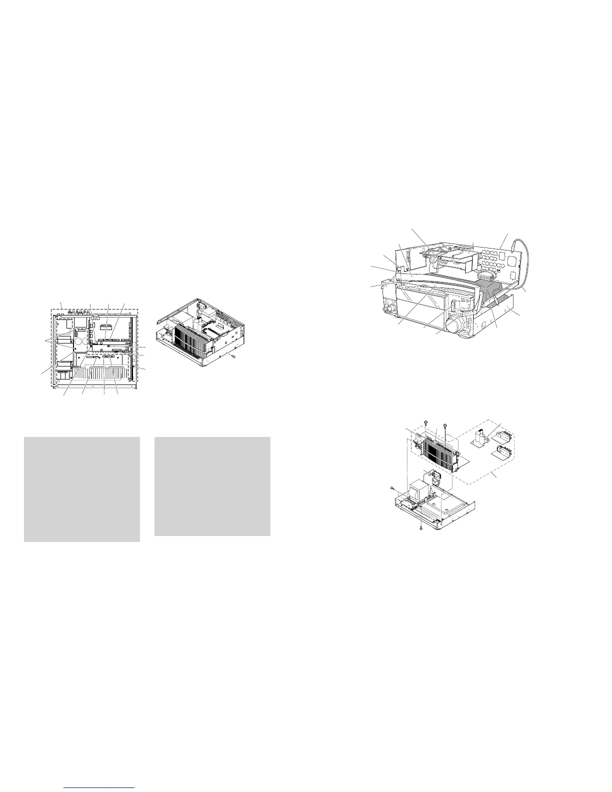
b. Remove 4 screws (G), 1 screw (H) and 1 screw (I).
(Fig. 7)
c. Remove CB16-18, CB20, CB303, CB406 and CB407.
(Fig. 7)
d. Remove the rear unit and MAIN (2) P.C.B.. (Fig. 7)
6. リアユニットの外し方
a.
E
のネジ9本、
F
のネジ4本を外します。(Fig.5)
b.
G
のネジ4本、
H
のネジ1本、
I
のネジ1本を外しま
す。(Fig.7)
c. CB16−18、CB20、CB303、CB406、407を外しま
す。
d. リアユニットおよびMAIN(2)P.C.B.を取り外します。
Fig. 7
When checking the DSP P.C.B.:
• Put the rubber sheet and the cloth over the equip-
ment. Then place the P.C.B.s upside down on the
cloth and check it. (Fig. 8)
• Reconnect all cables (connectors) that have been dis-
connected. Use the extension cable before servicing
the following section.
FL (1) P.C.B. CB901_FL (2) P.C.B. CB970:
MF126500 (26P, 500mm)
FL (2) P.C.B. CB971_OPERATION (2) P.C.B. CB803:
MF115500 (15P, 500mm)
• When connecting the flexible flat cable, be careful
with polarity.
• In main unit, the ground of rear unit is connected to the
chassis. When this rear unit are removed from chas-
sis, connect the ground to the chassis, using a ground
lead or such. (Fig. 8)
DSPP.C.B.チェックをする場合には:
・ 本機の上にゴムシートと布を敷き、その上にP.C.B.を
裏返しに置いてチェックします。(Fig.8)
・ 外したケーブル(コネクター)をすべて接続します。
ただし次の区間は、サービス用延長ケーブルを使用し
てください。
FL(1)P.C.B.CB901FL(2)P.C.B.CB970:
MF126500(26P、500mm)
FL(2)P.C.B.CB971OPERATION(2)P.C.B.CB803:
MF115500(15P、500mm)
・ フラットケーブルを接続する際、極性に注意してくだ
さい。
・ 本機ではリアユニットのアースがシャーシに接続されて
います。リアユニットをシャーシより取り外した場合
は、リード線等でアースをシャーシに接続してくださ
い。(Fig.8)
Fig. 8
Fig. 9
7. Removal of Amp Unit
a. Remove 2 screws (J), 5 screws (K) and 2 screws (L).
(Fig. 9)
b. Remove CB6, CB11, CB15 and CB253. (Fig. 9)
c. Remove the amp unit. (Fig. 9)
7. アンプユニットの外し方
a.
J
のネジ2本、
K
のネジ5本、
L
のネジ2本を外します。
(Fig.9)
b. CB6、CB11、CB15、CB253を外します。(Fig.9)
c. アンプユニットを取り外します。(Fig.9)
CB17 CB16CB20
CB18
CB407CB406CB303
Rear unit
リアユニット
G
H
I
G
MAIN (2)
P.C.B.
G
FUNCTION (1) P.C.B.
FL (2) P.C.B.
Rear unit
リアユニット
Ground lead
リード線
Rubber sheet and cloth
ゴムシートと布
DSP P.C.B.
MF115500
CB901
CB803
CB971
CB970
MF126500
Chassis
シャーシ
Amp unit
アンプユニット
J
K
K
L
CB6
CB253
CB15
CB11

 Loading...