17
RX-V2700/DSP-AX2700
RX-V2700/
DSP-AX2700
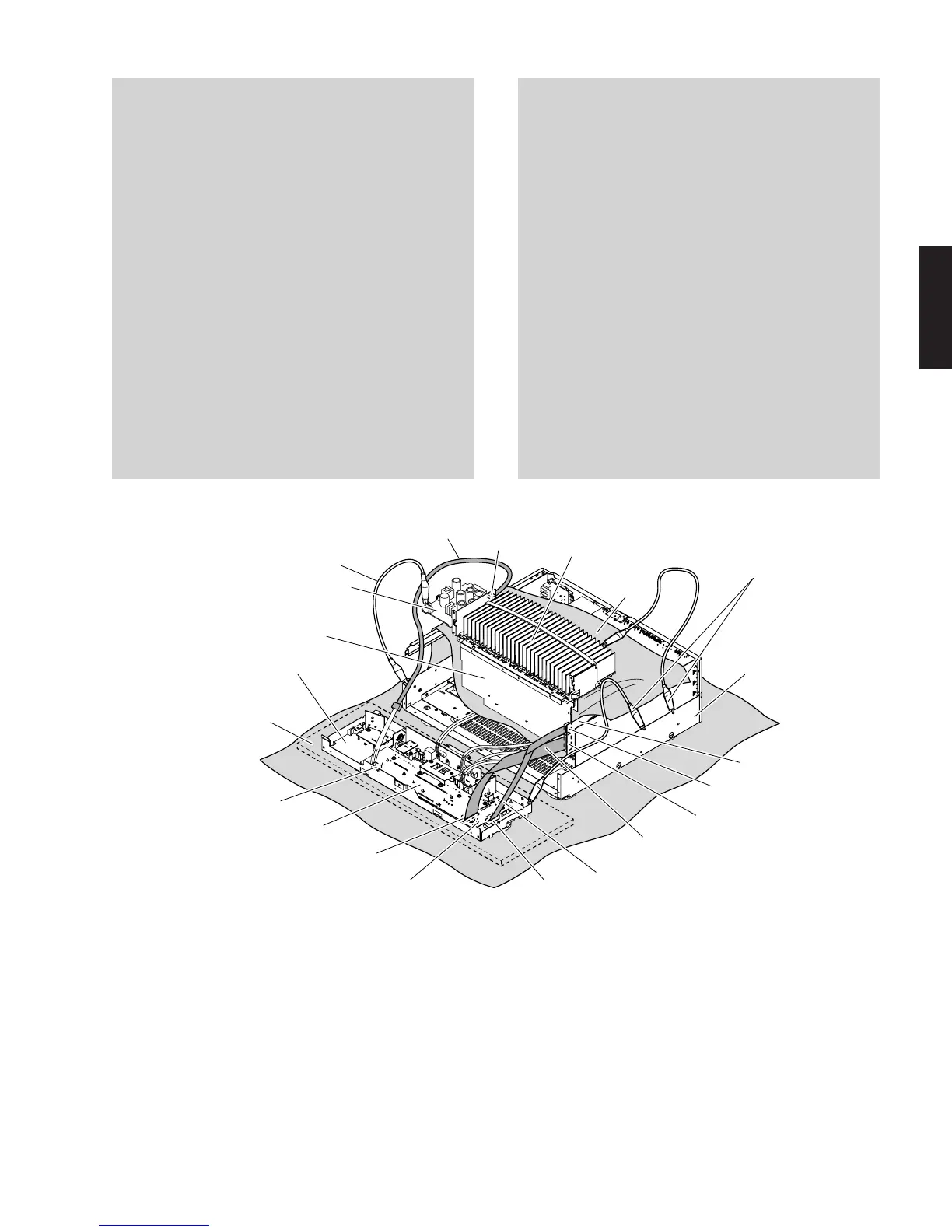
Fig. 10
MF405400
CB12
W9001
CB901
CB971
CB970
CB803
MF115500
MF126500
POWER (1) P.C.B.
MAIN (1) P.C.B.
OPERATION (2) P.C.B.
Sub chassis unit
サブシャーシユニット
Cloth
布
Chassis
シャーシ
FL (2) P.C.B.
FL (1) P.C.B.
Rubber sheet and cloth
ゴムシートと布
Ground lead
アース線
Amp unit
アンプユニット
Ground lead
アース線
アンプユニットをチェックをする場合には:
・ サブシャーシユニットをゴムシートと布の上に置きま
す。(Fig.10)
・ アンプユニットはヒートシンクといっしょに立てて
チェックします。(Fig.10)
・ 外したケーブル(コネクター)をすべて接続します。
ただし次の区間は、サービス用延長ケーブルを使用し
てください。
FL(1)P.C.B.CB901FL(2)P.C.B.CB970:
MF126500(26P、500mm)
FL(2)P.C.B.CB971OPERATION(2)P.C.B.CB803:
MF115500(15P、500mm)
FL(1)P.C.B.W9001POWER(1)P.C.B.CB12:
MF405400(5P、400mm)
・ フラットケーブルを接続する際、極性に注意してくだ
さい。
・ 本機ではサブシャーシユニットおよびアンプユニット
のアースがシャーシに接続されています。サブシャー
シユニットおよびアンプユニットをシャーシより取り
外した場合は、リード線等でアースをシャーシに接続
してください。(Fig.10)
When checking the Amp Unit:
• Place the sub chassis unit on top of the rubber sheet
and cloth. (Fig. 10)
• Put the amp unit together with the heat sink upright
and check them. (Fig. 10)
• Reconnect all cables (connectors) that have been dis-
connected. Use the extension cable before servicing
the following section.
FL (1) P.C.B. CB901_FL (2) P.C.B. CB970:
MF126500 (26P, 500mm)
FL (2) P.C.B. CB971_OPERATION (2) P.C.B. CB803:
MF115500 (15P, 500mm)
FL (1) P.C.B. W9001 _ POWER (1) P.C.B. CB12:
MF405400 (5P, 400mm)
• When connecting the flexible flat cable, be careful
with polarity.
• In main unit, the ground of sub chassis unit and amp
unit is connected to the chassis. When this sub chas-
sis unit and amp unit are removed from chassis, con-
nect the ground to the chassis, using a ground lead or
such. (Fig. 10)

 Loading...