RX-V557/HTR-5850/DSP-AX557
RX-V457/HTR-5840/DSP-AX457
23
RX-V557/HTR-5850/DSP-AX557
RX-V457/HTR-5840/DSP-AX457
8
7
7
9
9
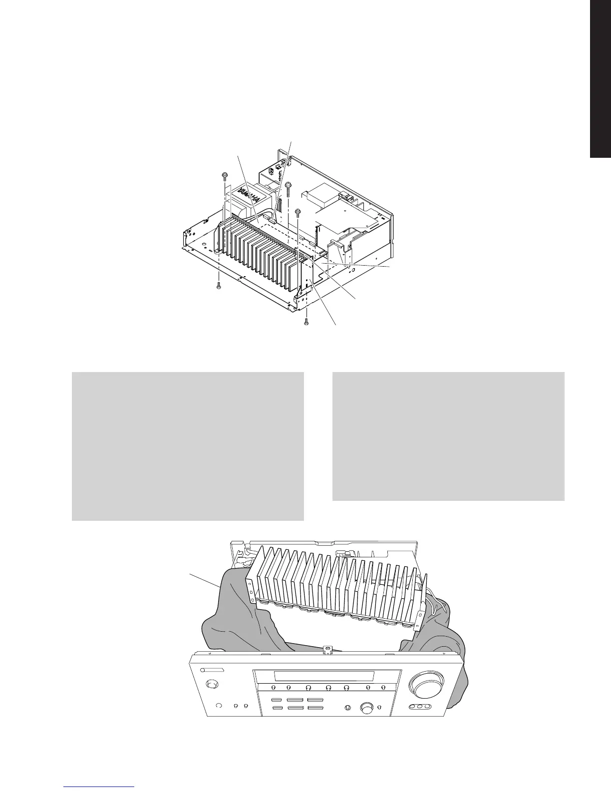
POWER (1) P.C.B.
POWER (2) P.C.B.
MAIN (5) P.C.B.
MAIN (1) P.C.B.
CB354
P.C.B.チェックをする場合には
・ 布を敷きます。その上にMAIN(1)、(5)、POWER
(1)、(2)P.C.B.をヒートシンクと一緒に立ててチェック
します。(Fig.6)
・ 外したケーブル(コネクター)をすべて接続してください。
・ フラットケーブルを接続する際、極性に注意してくださ
い。
・ リアパネルから外したP.C.B.はアースが浮いて動作しま
せんので、各P.C.B.のアースをリード線等でシャーシま
たはGNDに接続してください。
When checking the P.C.B.:
• Put a Cloth over the equipment. Put the MAIN (1), (5)
and POWER (1), (2) P.C.B.s together with the heat
sink upright on the Cloth and check them. (Fig. 6)
• Reconnect all cables (connectors) that have been
disconnected.
• When connecting the flat cable, use care for the
polarity.
• The P.C.B. removed from the rear panel does not
work because its grounding is loose. Be sure to
connect the ground of each P.C.B. to the chassis or
GND with a jumper wire or the like.
Fig. 6
5. MAIN(1)、(5)、POWER(1)、(2)P.C.B.の外し方
a. CB354を外します。(Fig.5)
b.
7
のネジ2本、
8
のネジ2本、
9
のネジ3本を外します。(Fig.
5)
c. MAIN(1)、(5)、POWER(1)、(2)P.C.B.を取り外しま
す。(Fig.5)
5. Removal of MAIN (1), (5) and POWER (1), (2) P.C.B.s
a. Remove CB354. (Fig. 5)
b. Remove 2 screws (7), 2 screws (8) and 3 screws
(9). (Fig. 5)
c. Remove MAIN (1), (5) and POWER (1), (2) P.C.B.s.
(Fig. 5)
Fig. 5
Cloth
布
 Loading...