RX-V540/RX-V540RDS/HTR-5650/HTR-5650RDS/DSP-AX540
RX-V440/RX-V440RDS/HTR-5640/HTR-5640RDS/DSP-AX440
RX-V540/RX-V540RDS/HTR-5650/HTR-5650RDS/DSP-AX540
RX-V440/RX-V440RDS/HTR-5640/HTR-5640RDS/DSP-AX440
18
CB305
CB306
CB605
Top Cover
Front Panel Unit
CB612
1
1
3
3
3
2
2
CB603
CB307
Support/DSP
CB104
CB602
4
DSP P.C.B.
CB304
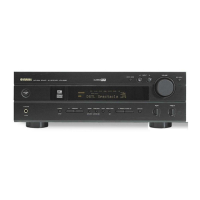
■ DISASSEMBLY PROCEDURES/分解手順
Fig. 1
(Remove parts in the order as numbered.)
Disconnect the power cable from the AC outlet.
1. Removal of Top Cover
a. Remove 4 screws (1) and 4 screws (2). (Fig. 1)
b. Slide the Top Cover rearward to remove it. (Fig. 1)
2. Removal of Front Panel Unit
a. Remove 5 screws (3) and then remove the Front Panel
Unit. (Fig. 1)
b. Loosen the harness fixture fixing the cable.
c. Remove CB305, CB306, CB605 and CB612. (Fig. 1)
1. トップカバーの外し方
12
2. フロントパネルユニットの外し方
3
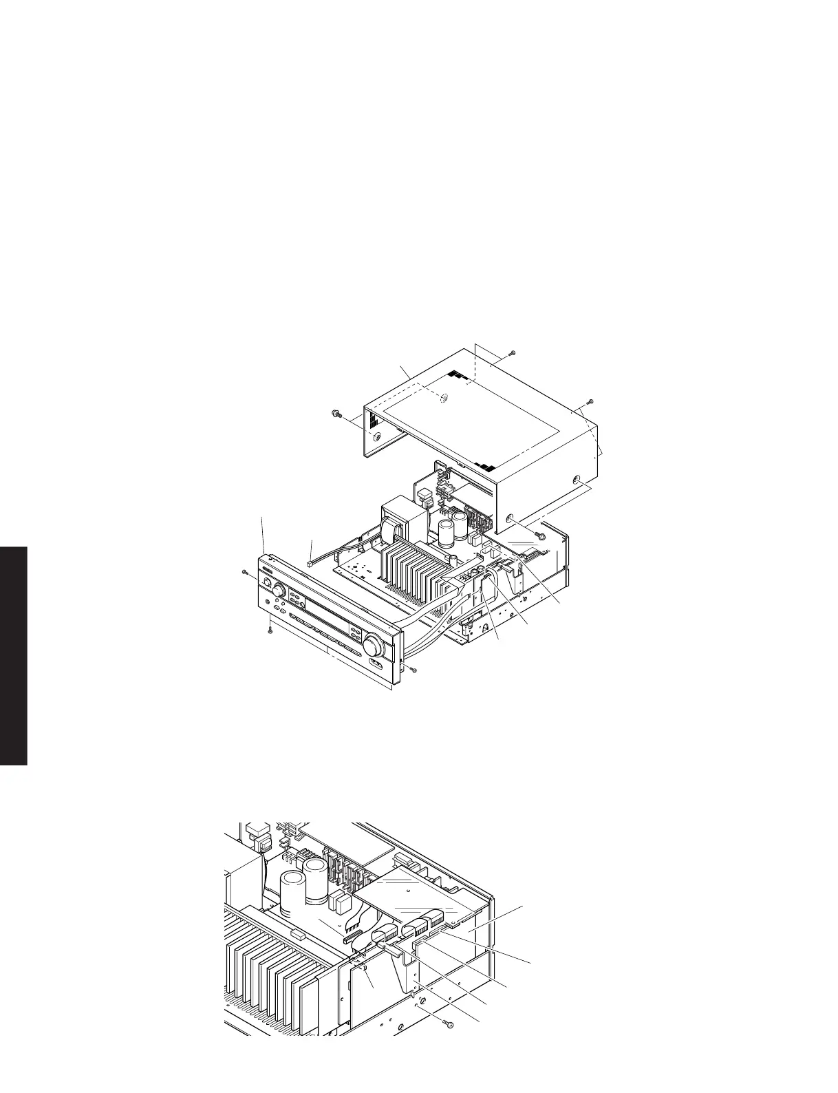
Fig. 2
3. DSPP.C.B.の外し方
4
5
3. Removal of DSP P.C.B.
a. Remove 1 screw (4). (Fig. 2)
b. Remove 6 screws (5). (Fig. 3)
c. Remove CB602 and CB603. (Fig. 2)
d. Remove the DSP P.C.B. with the Support/DSP. (Fig. 2)
 Loading...