– 14 –
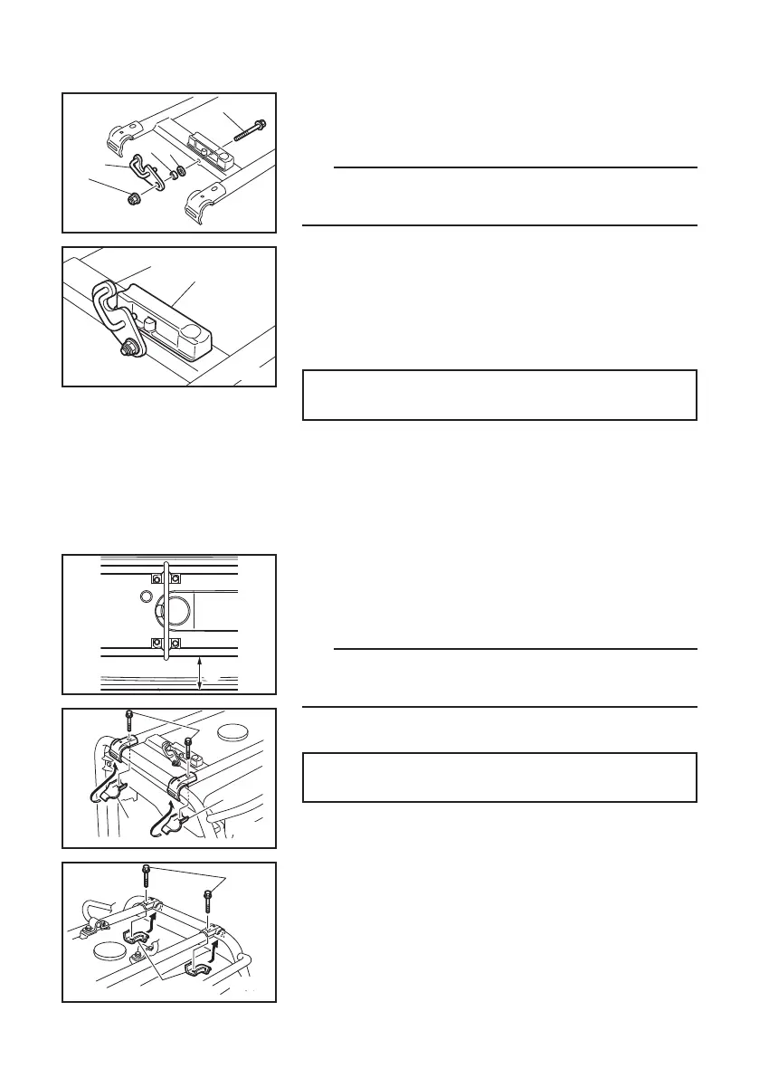
4. Place the carrier frame on the generator body so
that the lock lever is positioned on the left side of
the control panel. Fasten the plate to the carrier
frame with the bolts.
TIP
Place the carrier frame 10 cm (3.94 in) from the end of
generator body.
a 10 cm (3.94 in)
Tightening torque:
16 N·m (1.6 kgf·m, 12 lb·ft)
r Bolt (8 × 45 mm Flange bolt)
t Plate
3. Insert the bolt into the carrier frame, and then put
the washer, collar, and lock lever in this order, and
tighten the nut.
TIP
9 Make sure that the collar is placed into the washer.
9 Lock lever pin should be above stopper.
8 Nut (8 mm Flange nut [Self-locking nut])
9 Lock lever
0 Collar
q Washer (Plastic)
w Bolt (8 × 60 mm Flange bolt)
e Stopper
Tightening torque:
16 N·m (1.6 kgf·m, 12 lb·ft)
a
000-000
r
t
t
000-000
r
t
000-000
8
9
0
q
w
000-000
9
e
7P6-F8199-13.indd 14 2019/12/11 9:57:21