
J
Jesus PowellAug 4, 2025
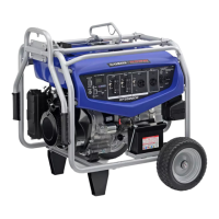
Why won't my Yamaha Portable Generator engine start?
- OOlivia CherryAug 4, 2025
If your Yamaha Portable Generator's engine won't start, several factors could be at play. Ensure fuel is being supplied to the combustion chamber and that there's fuel in the tank. Check that the fuel cock lever is in the ON position. A clogged fuel line or foreign matter in the fuel cock could also be the culprit, requiring cleaning. The carburetor might also be clogged and need cleaning. Insufficient oil levels can prevent starting, so add engine oil if the level is low. Finally, make sure the engine switch is set to the ON position.