GENERAL CHASSIS
3-2
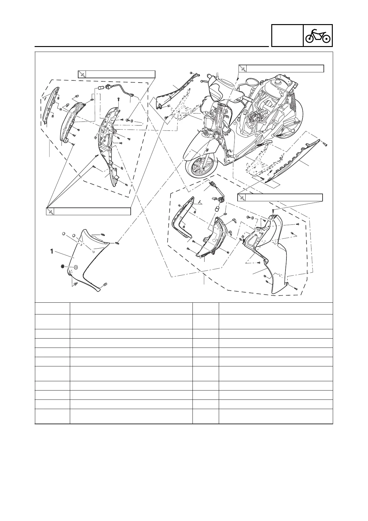
Removing the Front upper cover, front side covers assembly and side moles (For disc model)
Order Job/Parts to remove Q’ty Remarks
Rear side cover assembly
Refer to “GENERAL CHASSIS” on page
3-1.
1 Front upper cover 1
2 Lower side moles (LH & RH) 1+1
3 Turn signal light coupler 1 Disconnect.
4 Front side cover assembly (RH) 1
5 Front side cover assembly (LH) 1
Before removing disconnected turn signal
light coupler.
6 Turn signal light moles (LH & RH) 1+1
7 Turn signal light assembly (LH & RH) 1+1
8 Front side cover (LH & RH) 1+1
For installation, reverse the removal proce-
dure.
7
8
8
2
2
5
4
6
6
7
3
3
1.8 0.18 1.3N·m ( kgf·m, lb·ft)
7 0.7 5.2N·m ( kgf·m, lb·ft)
1.8 0.18 1.3N·m ( kgf·m, lb·ft)
1.8 0.18 1.3N·m ( kgf·m, lb·ft)
B7JF8197E1.book Page 2 Tuesday, June 29, 2021 2:28 PM
 Loading...