44 Chapter 4—Connections and Setup
01V96—Owner’s Manual
3 Press [ENTER] to confirm the change.
Patching Omni Outs
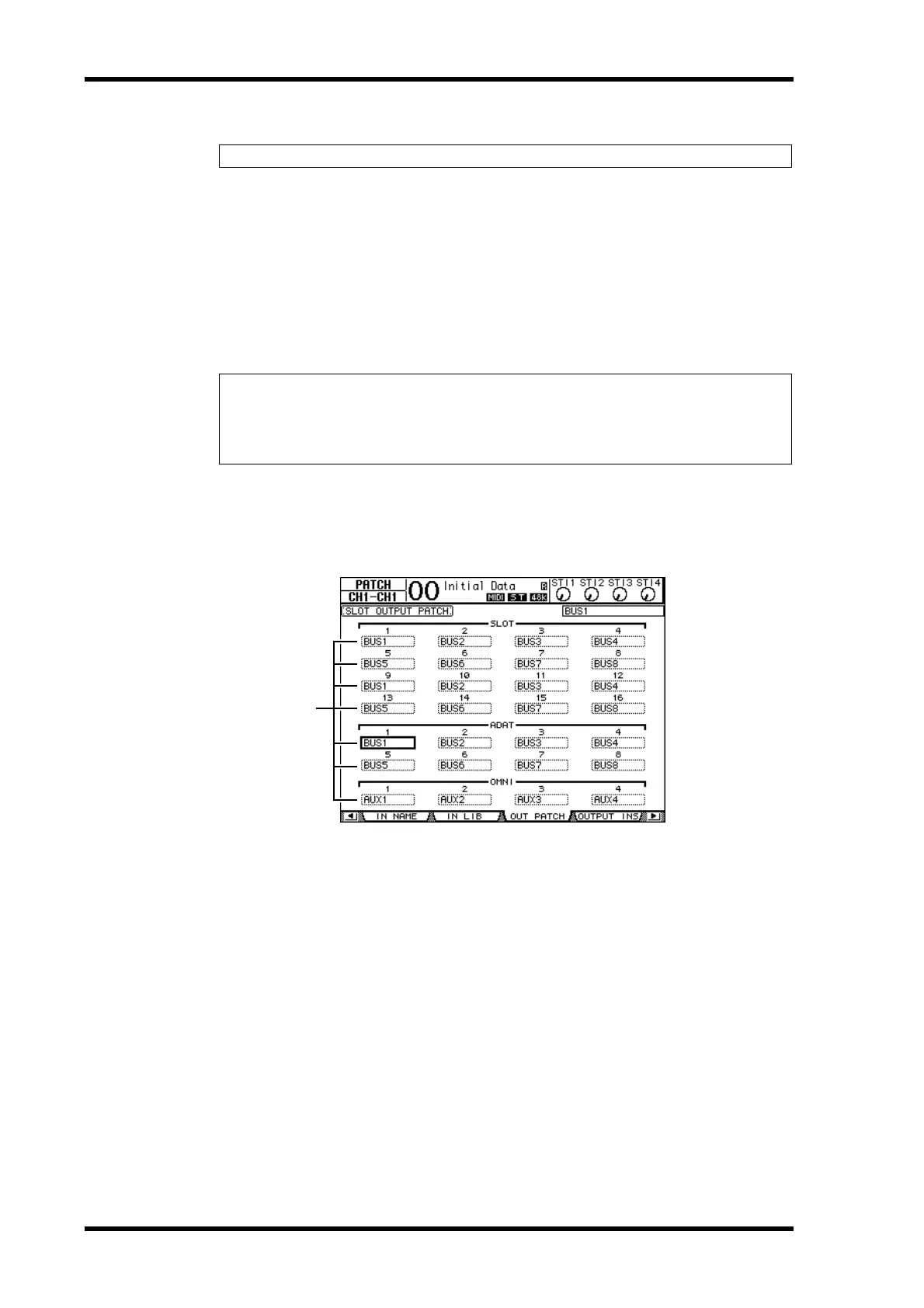
By default, the output connectors are patched as follows:
• OMNI OUT connectors 1–4 ..............Aux Out 1–4
• ADAT OUT channels 1–8...................Bus Out 1–8
• Slot channels 1–8.................................Bus Out 1–8
• Slot channels 9–16...............................Bus Out 1–8
• 2TR DIGITAL connectors..................Stereo Out L & R
Follow the steps below to view or change the patching.
1 Press the DISPLAY ACCESS [PATCH] button repeatedly until the following
page appears.
Signals that are currently assigned to the output connectors are shown in the parameter
boxes (
1) underneath the connector numbers. The parameter indicators are explained
below:
• - ..............................................................No assignment
• BUS1–BUS8..........................................Bus Out 1–8 signals
• AUX1–AUX8 ........................................Aux Out 1–8 Signals
• ST L/R....................................................Stereo Out signals
• INS CH1–INS CH32 ...........................Input Channels 1–32 Insert Outs
• INS BUS1–INS BUS8 ..........................Bus Out 1–8 Insert Outs
• INS AUX1–INS AUX8 .........................Aux Out 1–8 Insert Outs
• INS ST-L/ST-R......................................Stereo Out Insert Outs
• CAS BUS1–BUS8.................................Bus Out 1–8 Cascade Outs
• CAS AUX1–AUX8................................Aux Out 1–8 Cascade Outs
• CAS ST-L/ST-R.....................................Stereo Out Cascade Outs
• CASSOLOL/CASSOLOR....................Solo Channel Cascade Outs
Tip: To restore the default patching, recall Input Patch memory #00 (see page 174).
Tip:
• The STEREO OUT connectors always output the Stereo Bus signals.
• The MONITOR OUT connectors output monitor signals or the 2TR IN signals, depending
on the Monitor Source selector setting.
1





 To Next Page