THROTTLE BODIES
7-10
ECA17590
• Do not use a tool, such as a wire brush, to
remove the carbon deposits; otherwise, the
inside of the throttle bodies may be dam-
aged.
• Do not allow carbon deposits or other for-
eign materials to enter any of the passages
in each throttle body or in the space be-
tween the throttle valve shaft and the throt-
tle body.
f. After removing the carbon deposits, clean the
inside of the throttle bodies with the recom-
mended cleaning solvent, and then dry the
throttle bodies using compressed air.
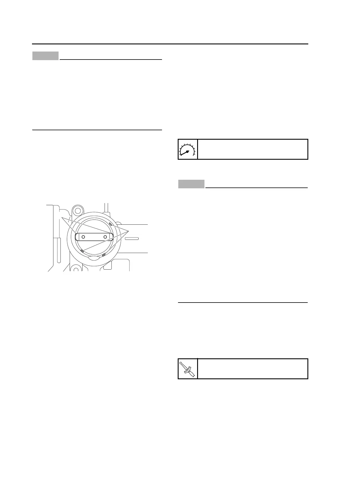
g. Make sure that there are no carbon deposits
or other foreign materials in any of the pas-
sages “a” in each throttle body or in the space
“b” between the throttle valve shaft and the
throttle body.
▲▲▲▲▲▲▲▲▲▲▲▲▲▲▲▲▲▲▲▲▲▲▲▲▲▲▲▲▲▲▲▲
3. Install the throttle bodies.
4. Reset:
• ISC (Idle Speed Control) learning values
Use the diagnostic code number “67”.
Refer to “SELF-DIAGNOSTIC FUNCTION
AND DIAGNOSTIC CODE TABLE” on page
9-5.
5. Adjust:
• Throttle bodies synchronizing
Out of specification Replace the throttle
bodies.
Refer to “SYNCHRONIZING THE THROT-
TLE BODIES” on page 3-10.
EAS31160
REPLACING THE THROTTLE BODIES
1. Remove the throttle bodies from the vehicle.
2. Install a new throttle bodies to the vehicle.
3. Reset:
• ISC (Idle Speed Control) learning values
Use the diagnostic code number “67”.
Refer to “SELF-DIAGNOSTIC FUNCTION
AND DIAGNOSTIC CODE TABLE” on page
9-5.
4. Adjust:
• Throttle bodies synchronizing
Refer to “SYNCHRONIZING THE THROT-
TLE BODIES” on page 3-10.
5. Place the vehicle on a maintenance stand so
that the rear wheel is elevated.
6. Check:
• Engine idling speed
Start the engine, warm it up, and then mea-
sure the engine idling speed.
EAS30480
INSTALLING THE INJECTORS
ECA21550
• Always use new O-rings.
• When installing the injectors, do not allow
any foreign material to enter or adhere to
the injectors, fuel rails, or O-rings.
• Be careful not to twist or pinch the O-rings
when installing the injectors.
• When installing the injector, install it at the
same position as the removed cylinder.
• If an injector is subject to strong shocks or
excessive force, replace it.
• If installing the original fuel rail and bolts,
remove the white paint marks using a
cleaning solvent. Otherwise, paint chips on
the bolt seats could prevent the bolts from
being tightened to the specified torque.
1. Install a new seal onto the end of each injec-
tor.
2. Install the injectors “1” to the fuel rails “2”.
3. Install the injector joint “3”, making sure to in-
stall them in the correct direction.
4. Install the injector assemblies to the throttle
bodies.
Engine idling speed
1200–1400 r/min
Fuel rail screw (throttle body)
3.5 N·m (0.35 kgf·m, 2.5 lb·ft)



 To Next Page