SERVICE MANUAL
HAMAMATSU, JAPAN
SERVICE MANUAL
PK
001811
Copyright (c) Yamaha Corporation. All rights reserved. PDF ’08.09
SPECIFICATIONS (Tyros3) ........................................ 3
SPECIFICATIONS (TRS-MS02) ................................. 5
PANEL LAYOUT (Tyros3) ........................................... 6
PANEL LAYOUT (TRS-MS02) .................................... 8
CIRCUIT BOARD LAYOUT ......................................... 9
DISASSEMBLY PROCEDURE (Tyros3) ...................11
DISASSEMBLY PROCEDURE (TRS-MS02) ........... 24
INSTALLING THE OPTIONAL DIMMS ..................... 26
REPLACING THE INTERNAL HARD DISK ............. 28
LSI PIN DESCRIPTION ............................................ 30
IC BLOCK DIAGRAM ............................................... 44
CIRCUIT BOARDS ................................................... 47
TEST PROGRAM ..................................................... 78
INITIAL SETTING ....................................................111
CONTENTS
FORMATTING HDD ................................................113
SYSTEM RESET .....................................................114
OS UPDATE ............................................................116
INITIALIZING INTERNET SETTINGS .....................118
DATA BACKUP ........................................................119
DISPLAY MESSAGES ........................................... 120
SYSTEM BOOTING FLOWCHART ....................... 123
MIDI IMPLEMENTAION CHART ............................ 125
MIDI DATA FORMAT .............................................. 126
PARTS LIST
BLOCK DIAGRAM
WIRING
OVERALL CIRCUIT DIAGRAM
/ TRS-MS02
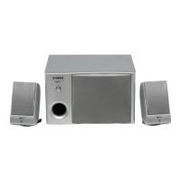
MONITOR SPEAKER
TRS-MS02
Tyros3