ELECTRICAL COMPONENTS
8-60
Set the charging time at 20 hours (maximum).
e. Measure the battery open-circuit voltage after
leaving the battery unused for more than 30
minutes.
▲▲▲▲▲▲▲▲▲▲▲▲▲▲▲▲▲▲▲▲▲▲▲▲▲▲▲▲▲▲▲▲
6. Install:
• Battery
7. Connect:
• Battery leads
(to the battery terminals)
ECA13630
First, connect the positive battery lead “1”,
and then the negative battery lead “2”.
8. Check:
• Battery terminals
Dirt Clean with a wire brush.
Loose connection Connect properly.
9. Lubricate:
• Battery terminals
10.Install:
• Seat
• Side cover (left/right)
Refer to “GENERAL CHASSIS” on page 4-1.
EAM30292
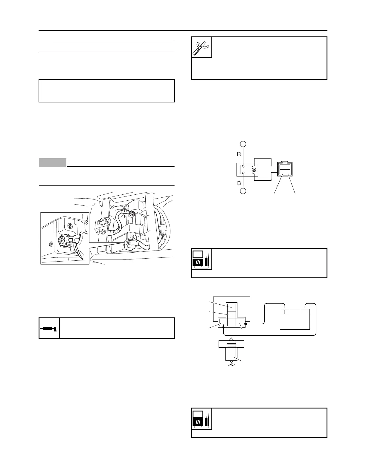
CHECKING THE RELAYS
Check each switch for continuity with the digital
circuit tester. If the continuity reading is incor-
rect, replace the relay.
1. Disconnect the relay from the wire harness.
2. Connect the digital circuit tester () and bat-
tery (12 V) to the relay terminal as shown.
Check the relay operation.
Out of specification Replace.
Starter relay
Main relay
12.8 V or more --- Charging is complete.
12.7 V or less --- Recharging is required.
Under 12.0 V --- Replace the battery.
Recommended lubricant
Dielectric grease
2
1
Digital circuit tester (CD732)
90890-03243
Model 88 Multimeter with tachom-
eter
YU-A1927
1. Positive battery terminal
2. Negative battery terminal
3. Positive tester probe
4. Negative tester probe
Result
Continuity
(between “3” to “4”)
1. Positive battery terminal
2. Negative battery terminal
3. Positive tester probe
4. Negative tester probe
Result
Continuity
(between “3” to “4”)
 Loading...