HANDLEBAR
4-38
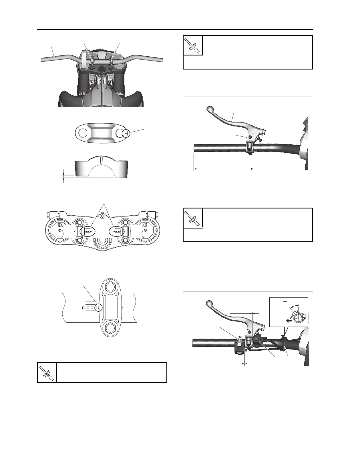
3. Tighten:
• Lower handlebar holder nut
4. Install:
• Clutch lever holder “1”
• Clutch lever “2”
The clutch lever holder “1” should be installed
according to the dimensions shown.
5. Install:
• Engine stop switch “1”
• Mode switch “2”
• Clamp “3”
• The engine stop switch “1” and the mode
switch “2” should be installed according to the
dimensions shown.
• Pass the engine stop switch lead through the
middle of the clutch lever holder.
6. Install:
• Handlebar grip “1”
a. Slightly coat the handlebar left end with a
rubber adhesive.
b. Install the handlebar grip on the handlebar
by pressing the grip from the left side.
c. Wipe off any excess adhesive with a clean
cloth.
Lower handlebar holder nut
40 N·m (4.0 kgf·m, 30 lb·ft)
3
44
b
+1
+2
-1
-2
+1
+2
-1
-2
c
+1
+2
-1
-2
d
Clutch lever holder bolt
5 N·m (0.5 kgf·m, 3.7 lb·ft)
Clutch lever nut
4.0 N·m (0.40 kgf·m, 3.0 lb·ft)
Engine stop switch screw
0.5 N·m (0.05 kgf·m, 0.37 lb·ft)
Screw (mode switch)
1.3 N·m (0.13 kgf·m, 0.95 lb·ft)
2
1
(6.61 in)
168 mm
0mm
(0 in)
0mm
(0 in)
1
2 3
DFW
30 50˚




 To Next Page