CYLINDER AND PISTON
5-34
EAM30096
REMOVING THE PISTON
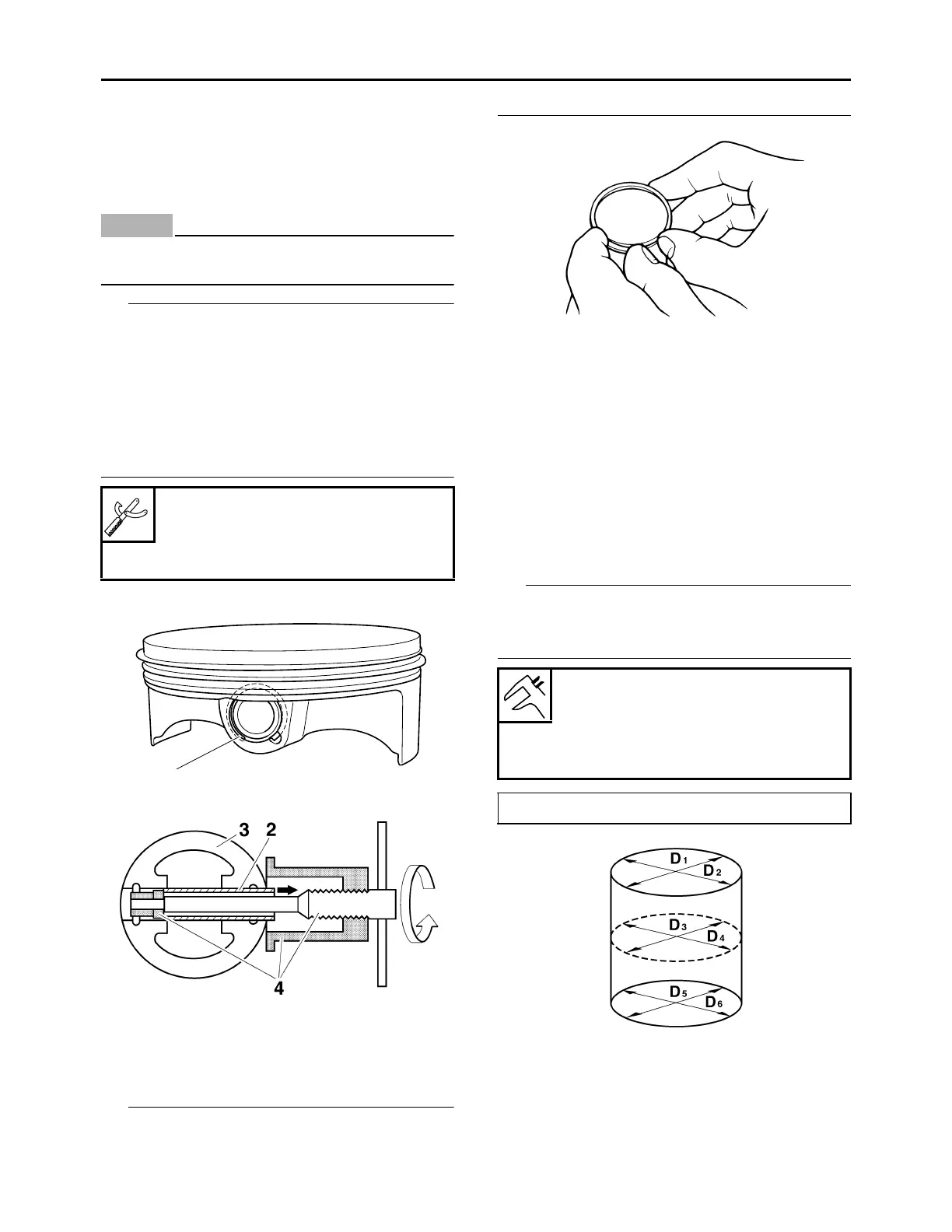
1. Remove:
• Piston pin clip “1”
• Piston pin “2”
• Piston “3”
ECA13810
Do not use a hammer to drive the piston pin
out.
• Before removing the piston pin clip, cover the
crankcase opening with a cloth to prevent the
piston pin clip from falling into the crankcase.
• Before removing the piston pin, deburr the pis-
ton pin clip’s groove and the piston pin’s bore
area. If the piston pin groove is deburred and
the piston pin is still difficult to remove, use the
piston pin puller set “4”.
2. Remove:
• Top ring
• 2nd ring
• Oil ring
When removing a piston ring, open the end gap
with your fingers and lift the opposite end gap of
the piston ring over the piston crown.
EAM30097
CHECKING THE CYLINDER AND PISTON
1. Check:
• Piston wall (Sidewall)
• Cylinder wall
Vertical scratches Replace the cylinder,
and replace the piston and piston rings as a
set.
2. Measure:
• Piston-to-cylinder clearance
a. Measure the cylinder bore “C” with the cyl-
inder bore gauge.
Measure the cylinder bore “C” by taking side-to-
side and front-to-back measurements of the cyl-
inder.
b. If out of specification, rebore or replace the
cylinder, and replace the piston and the
piston rings as a set.
c. Measure the piston outside diameter “a” at
the measuring point (from piston skirt bot-
tom) “b” with the micrometer.
Piston pin puller set
90890-01304
Piston pin puller
YU-01304
Bore
97.000–97.010 mm (3.8189–
3.8193 in)
Wear limit
97.060 mm (3.8213 in)
“C” = maximum of D
1
, D
2
, D
3
, D
4
, D
5
, D
6




 To Next Page