Yamatake Corporation Operation of the Transmitter
ST3000 Smart Transmitter Series 900 Electronic Differential Pressure/Pressure Transmitter 5-51
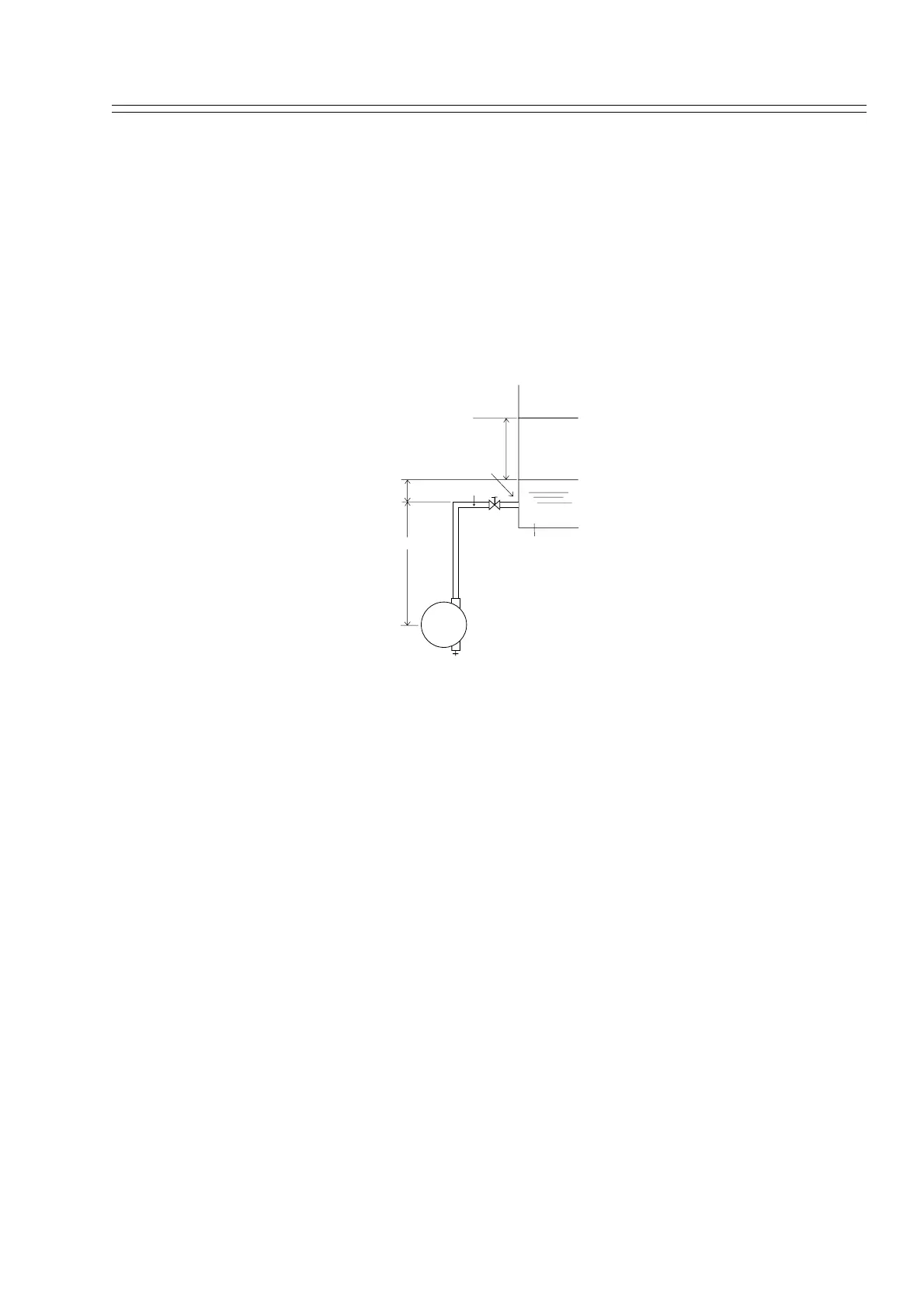
Set range calculation Ex. STG Type
Calculate the set range using these procedures:
The following symbols are used to express density and distance.
It is assumed that the density is fixed, during liquid level measurement.
:Specific gravity of liquid in tank
:Specific gravity of liquid in connecting pipe
l :Distance between 100% liquid level and 0% liquid level (measurement range)
h :Distance between 0% liquid level and high-pressure outlet port
d :Distance between high-pressure outlet port and transmitter
Figure 5-8
Pressure at 0% liquid level = h + d = LRV
Pressure at 100% liquid level = l + h + d = (l+h)r+ d = URV
Therefore, set the range as follows:
Low limit (LRV): h+ d ; High limit (URV): (l+h) + d
Example of calculation:
l = 1500 mm, h = 250 mm, d = 500 mm
= 0.9, = 1.0
If the above conditions are assumed, the following results are obtained:
Differential pressure at 0% liquid level = (250 x 0.9) + (500 x 1.0) = 725 mmH
2
O =
7.110 kPa
Differential pressure at 100% liquid level = {(1500 + 250) x 0.9) + (500 x 1.0) = 2075
mmH
2
O = 20.35 kPa
Therefore, set the range as follows:
Low limit (LRV): 7.110 kPa{725 mmH
2
O}, High limit (URV): 20.35 kPa{2075
mmH
2
O}
ρ
ρ
0
STG
d
h
ρ
l
ρo
100% liquid level
0% liquid level
Open tank
High-pressure outlet port
ρρ
0
ρρ ρ
0
ρ
0
ρρ
0
ρρ
0
ρρ
0