Chapter 3 Fuel Injection Equipment
_3_.
_D_is_a_s_se_m_b_l_J_',
_R_e_a_ss_e_m_b_l_y_a_n_d_L_n_s_p_e_ct_io_n_of_F_u_el_I_n_j_ec_t_io_n_P_um_._P
________
3
,4JH3(B)(C)E
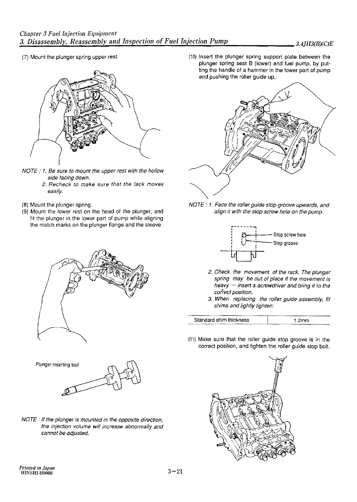
(7) Mount the plunger spring upper
rest
NOTE
: 1 _
Be
sure
to
mount
the upper rest with the hollow
side facing down.
2.
Recheck to make sure that the
lack
moves
easily.
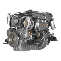
(8) Mount the plunger spring_
(9) Mount the lower rest
on
the head of the plunger, and
fit the plunger
in
the lower part of pump while aligning
the match marks
on
the plunger flange and the sleeve.
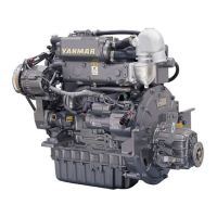
Plunger
inserting
tool
NOTE
:
If
the
plunger
is mounted in the opposite direction,
the injection volume will increase abnormafly
and
cannot be adjusted.
Printed
in Japan
HINSHI-H8009
3-21
(10)
Insert the plunger spring support plate
between
the
plunger spring seat
8 (lower) and fuel pump, by
put·
ting
the
handle
of
a hammer
in
the
lower
part
of
pump
and pushing the roller guide up.
NOTE
:
1.
Face the roller guide stop groove upwards,
and
align it with the stop
screw
hole
on
the pump,
~------..,
i ,,,.- I
:
o-~:--
Stop
screw
hole
: i
J--
:
Stop
groove
' - f
2.
Check the movement
of
the rack. The plunger
spring
may
be
out
of
place
if
the movement is
heavy -
insert a acrewdriver
and
bring it to the
correct position_
3.
When replacing the roffer guide assembly, fit
shims
and
lightly tighten:
Standard shim thickness
1.2mm
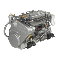
(11)
Make sure that the roller guide stop groove is
fn
the
correct position, and tighten the roller guide stop
bolt