Chapter 3 Fuel Injection Equipment
9. Pump Reassembly, Adjustment and Inspection
4LHA Series
Fig.
4
(
V
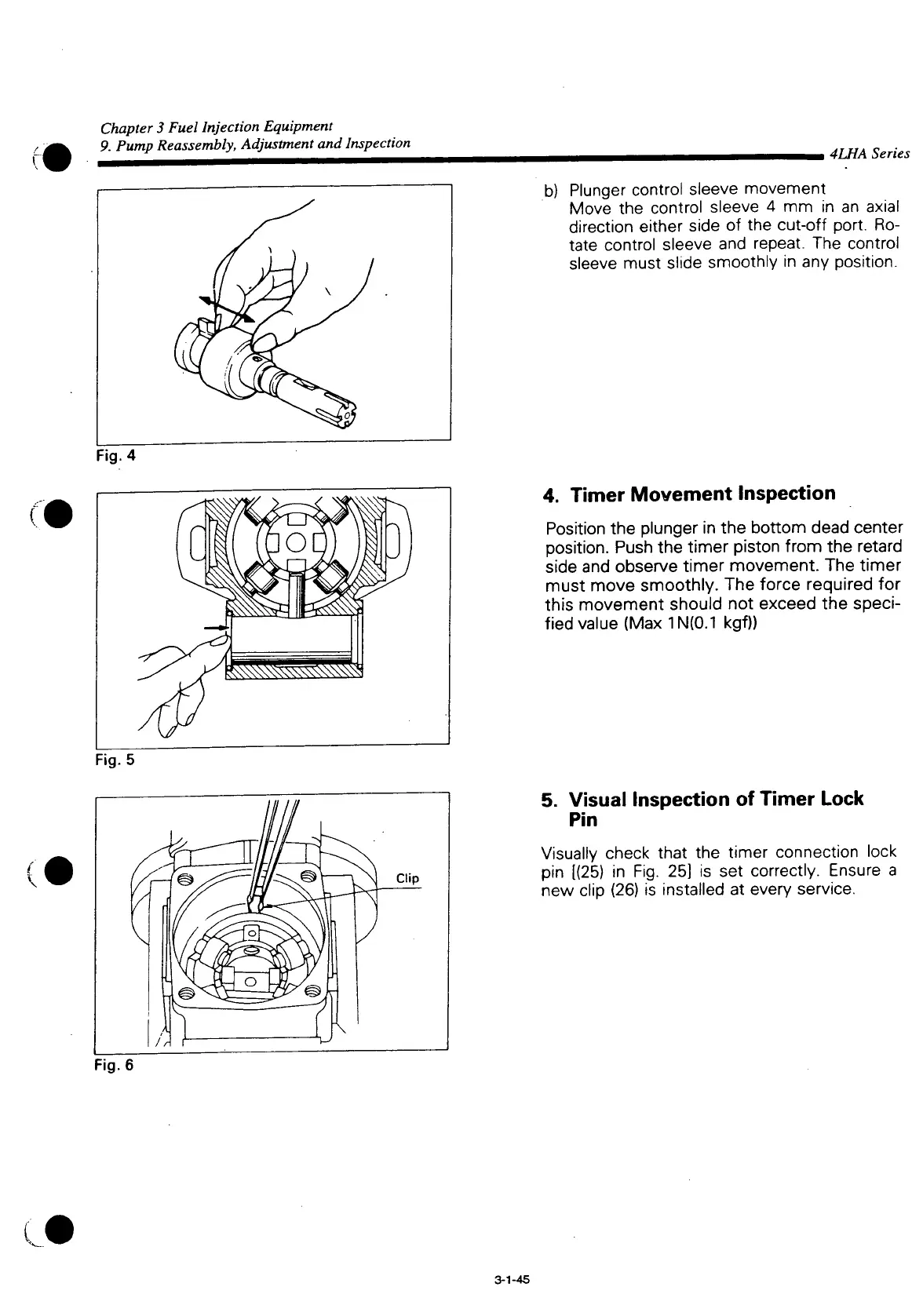
b) Plunger control sleeve movement
Move
the control sleeve 4 mm in an axial
direction either side of the
cut-off
port.
Ro-
tate
control sleeve and repeat. The control
sleeve
must slide smoothly in any position.
4.
Timer
Movement
Inspection
Position
the plunger in the bottom dead center
position.
Push
the timer piston from the retard
side
and observe timer movement. The timer
must move smoothly. The force required for
this movement should not exceed the
speci-
fied value (Max1N(0.1 kgf))
5. Visual
Inspection
of
Timer
Lock
Pin
Visually
check
that
the timer connection lock
pin [(25) in Fig. 25] is set correctly. Ensure a
new clip (26) is installed at every service.
Fig.
6
(J
3-1-45
 Loading...


