Chapter 3 Fuel Injection Equipment
4. Adjustment of Fuel Injection Pump and Governor
4LHA Series
Pump
rpm (N4)
200 rpm
Rack
indicator
scale
13.5
~ 14.5
Measuring
stroke
500st
Injection volume
See separate service
data
4-75 Check
injection
stop
Drive the pump at no load maximum rpm (N
2
). With
governor control lever in the
full
load position, operate
the stop lever on the governor
case,
and make sure
that
injection to all cylinders is stopped.
4-8
Adjustment
of
torque
rise
There
are some models which obtain torque rise
with
angleich
and torque springs incorporated in the fuel
injection pump as an injection volume increasing
mechanism.
Angleich
spring
I
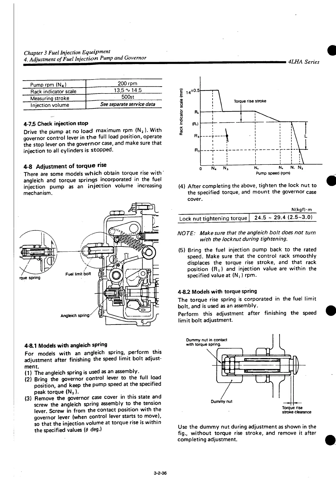
14
±0.5
•o
R.
(R.)
R3
Torque rise stroke
N,
N. N, Nj
Pump
speed (rpm)
(4) After completing the above, tighten the lock nut to
the specified torque, and mount the governor
case
cover.
N(kgf)m
Lock
nut tightening torque
24.5 ~ 29.4
(2.5-3.0)
NO TE: Make sure that the angleich bolt does not turn
with the locknut during tightening.
(5) Bring the fuel injection pump back to the rated
speed.
Make sure
that
the control rack smoothly
displaces
the torque rise stroke, and
that
rack
position (R,) and injection value are within the
specified
value at (N!) rpm.
4-8.2 Models
with
torque spring
The
torque rise spring is corporated in the fuel
limit
bolt, and is used as an assembly.
Perform
this adjustment after finishing the speed
limit
bolt adjustment.
4-8.1 Models
with
angleich
spring
For
models
with
an angleich spring, perform this
adjustment after finishing the speed
limit
bolt adjust-
ment.
(1) The angleich spring is used as an assembly.
(2) Bring the governor control lever to the
full
load
position,
and keep the pump speed at the specified
peak
torque (N
5
).
(3) Remove the governor
case
cover in this state and
screw
the angleich spring assembly to the tension
lever.
Screw in from the contact position
with
the
governor lever (when control lever starts to move),
so
that
the injection volume at torque rise is within
the specified values [8 deg.)
Dummy nut in contact
with
torque spring.
J UL J
Dummy nut
Torque rise
stroke clearance
Use
the dummy nut during adjustment as shown in the
fig.,
without torque rise stroke, and remove it after
completing adjustment.
3-2-36

 Loading...


