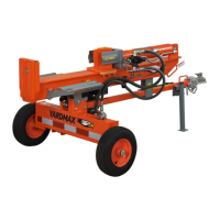
5. Disassemble the support leg from the unit. (Remove the bolts
and nuts, see Figure 2c.)
SPLIT CONTROL LEVER
1. Holding the hydraulic cylinder handle, pull out the cylinder
slowly and in a straight line until the output shaft in the
cylinder is against the trunnion mount and locked in the
U-shaped groove.
2. The control handle is shipped hanging from the valve on the
handle link. Remove the pin and cotter pin from the control
handle. Move the control lever to the vertical Neutral positon
(shown in circle on illustration Figure 3.)
3. Reinstall the pin and cotter pin to the control handle.
Loosen two M10 nuts by using a 16mm wrench. Change the handle
from the vertical position to the horizontal position. Secure and
tighten the two M10 nuts. (See Figure 4)
HYDRAULIC CYLINDER HANDLE
Hydraulic Cylinder Handle
Vertical Position
Horizontal Position
Pivot Bolt
U-Shaped Bracket
Pivot Hole
Bridge Pin
Trunnion Mount
Pin
Cotter Pin
Hydraulic Cylinder Handle
Output Shaft
18 X 135 X 1
1
Bridge Pin X 1
16 mm
16 mm
X 2
YS2565PM01 - 1609
12
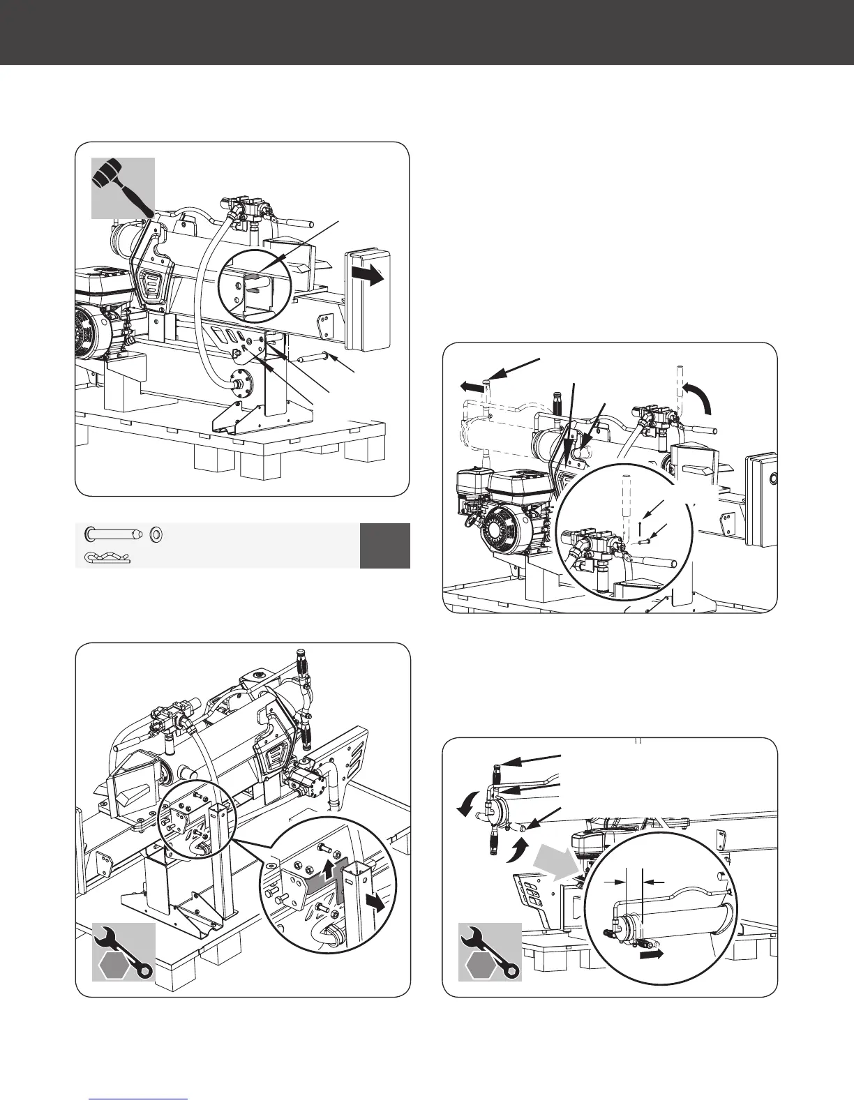
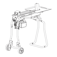
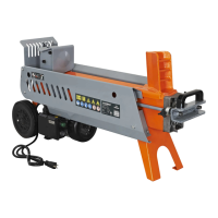
Gas Log Splitter
»
Operator’s Manual
Assembly
|
Figure 4
Figure 3
Figure 2c
Figure 2b
65876US25M101.indd 12 2016/8/26 11:10:31