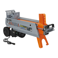
15. Put the axle with one wheel below the upper bracket. Make
sure the wheel is on the engine side. Align the holes in the
lower bracket and upper bracket. Insert and tighten bolt 1 and
bolt 2 rst, then tighten bolt 3 and bolt 4.
M12x30 (x4)
Upper Bracket of Axle
Lower Bracket of Axle
1.
2.
3.
4.
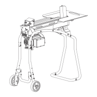
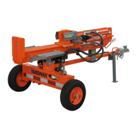
16. Rotate the bottom pallet slowly until there is enough space to
assemble the other wheel.
17. Use one hand to lift the tow bar slightly. Use the other hand to
move the wooden support block under the hydraulic tank and
engine, so it sits level.
3
1
4
2
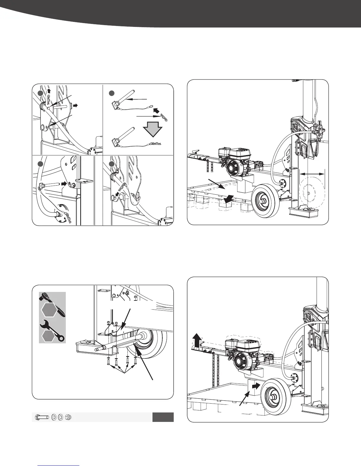
Bridge Pin
Lower Hole
Upper Hole
Hydraulic Cylinder Handle
Lock Pin
14. Move the bridge pin and lock pin from the upper hole to the
lower hole. Make sure the bridge pin is connected to the wire
rope rst and then insert the lock pin. (See Figure 7g)
M12 X 30 X 4
5
18 mm
19 mm
YS2565PM01 - 1609
15
|
Assembly
Figure 7j
Figure 7i
Figure 7h
Figure 7g
65876US25M101.indd 15 2016/8/26 11:10:33