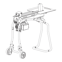
MUFFLER (YS2565 / YS2865 ONLY)
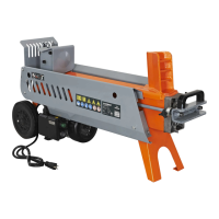
1. Remove the cap of the manual tube. Align the holes in the
manual tube with the holes in the tow bar, insert and tighten
bolts and washers. (See Figure 11)
2. Reattach the cap.
1. Remove the plastic sheet by loosening and removing the nuts
and washers, using a 13mm wrench.
2. Install the mufer by aligning the screw holes on the mufer to
the screw holes on the engine. Reinstall the washer and nuts,
using a 13mm wrench.
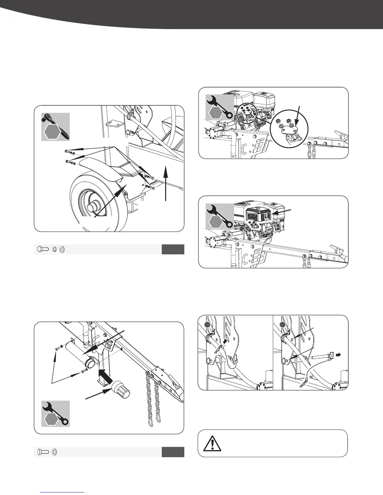
MANUAL TUBE
Align the left fender to the tank assembly. Insert the M8x20 bolts,
spring washers, at washers, and tighten by using a 13mm wrench.
(See Figure 10)
Follow the same procedure to assemble the right fender.
M8x20 (x8)
Fender (Left)
Tank Assembly
FENDER
VERTICAL POSITION TO HORIZONTAL POSITION
1. Remove the bridge pin and lock pin from the lower hole.
2. Hold the hydraulic cylinder handle and slowly lower the beam.
Insert the lock pin into the upper hole. Make sure the beam is
locked in the horizontal position.
3. Attach the bridge pin in the lock pin.
1 2
1
2
Lower Hole
Upper Hole
Upper Hole
Hydraulic Cylinder Handle
M8 X 20 X 8
9
M8 X 20 X 2
10
13 mm
13 mm
Do not let the beam suddenly drop. Keep hands and
ngers clear of pinch or crush points at all times.
13 mm
13 mm
YS2565PM01 - 1609
17
|
Assembly
Figure 13a
Figure 12a
Figure 11
Figure 10
Figure 12b
65876US25M101.indd 17 2016/8/26 11:10:34