Wheel Washer (x1)
Cotter Pin (x1)
Axle Nut (x1)
Wheel Cap (x1)
Roller Bearing (x2)
Anti-dust Washer (x1)
Valve Stem (x1)
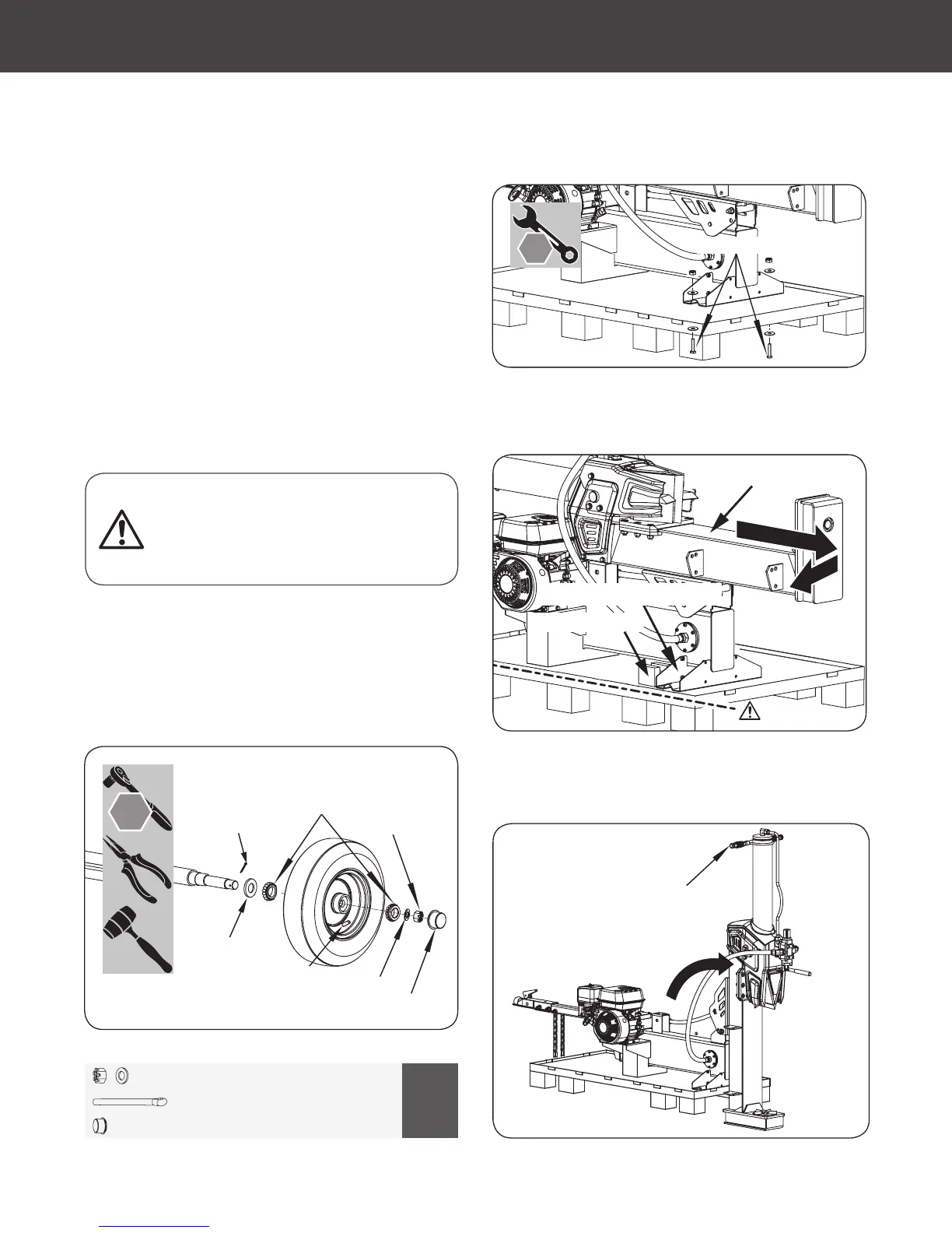
11. Remove the two M8x45 bolts, at washers, and nuts.
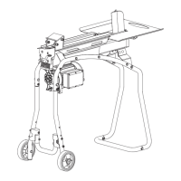
12. Hold the beam and move the unit until the upper bracket of the
wheel axle is against the wooden block.
Wooden Block
Upper Bracket of Wheel Axle
Beam Assembly
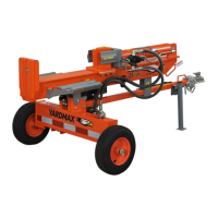
13. Hold the hydraulic cylinder handle and slowly stand the assembled
beam on the end plate in the vertical position.
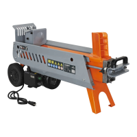
3. Slide the anti-dust washer and one roller bearing onto the axle.
Use a soft-faced hammer to tap the roller bearing lightly to
make sure the bearing is in the right position.
4. Slide the wheel with the valve stem facing out to the wheel
axle and the other roller bearing, then put the wheel washer
against the bearing. Use a 32mm socket to tighten the axle nut
completely. (See Figure 7c)
5. Turn the wheel to ensure proper bearing seating.
6. Loosen the axle nut until loose enough to turn the wheel with
your ngers.
7. Retighten the axle nut until "nger tight."
8. Insert the cotter pin through the hole in axle. Bend and spread
the prongs in opposite directions so the axle nut will not come
off (make sure the tire spins freely).
9. Use a soft-faced hammer to tap the anti-dust washer in the
right position.
10. Align the wheel cap against the wheel hub. Using a soft-faced
hammer, tap lightly to make sure to install the wheel cap onto
the wheel hub properly. (Only assemble one side of the wheel
assembly. The other side will be assembled when mounting the
entire assembly to the unit.)
3
1
4
2
Bridge Pin
Lower Hole
Upper Hole
Hydraulic Cylinder Handle
Lock Pin
M22 X 1
4
4 X 50 X 1
X 1
13 mm
X 2
32 mm
Installation of the cotter pin is important and
required. Failure to install the cotter pin can result in
loss of wheel retention. Always assemble using a new
cotter pin. Do not reuse.
YS2565PM01 - 1609
14
Gas Log Splitter
»
Operator’s Manual
Assembly
|
Figure 7f
Figure 7e
Figure 7d
Figure 7c
65876US25M101.indd 14 2016/8/26 11:10:33