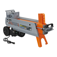
1. Align the support leg to the upper hole on the unit. Insert the
U-shaped lock pin to hold the support leg in place.
2. Slightly lift the machine by the tow bar while rotating it so that
the support leg can drop to the down position supporting the
machine on the ground
3. Fully insert the U-shaped lock pin. Make sure the short-end go
through the lower hole.
4. To secure the U-Shaped lock pin. Insert the roll pin thru
the location hole at the top of the support leg and into the
U-shaped lock pin hole.
5. Slide the spring and at washer over the end of the U-shaped
lock pin. Secure them in place with the other roll pin.
SUPPORT LEG
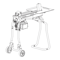
When mounting the lock latch assembly, make sure the latch rod
side of the bracket is opposite the engine. Install the horizontal
beam lock to the beam by using beam lock M10x25 bolts, spring
washers, and at washers. (See Figure 8)
HORIZONTAL BEAM LOCK
M10x25 (x2)
Horizontal Beam Lock
Beam
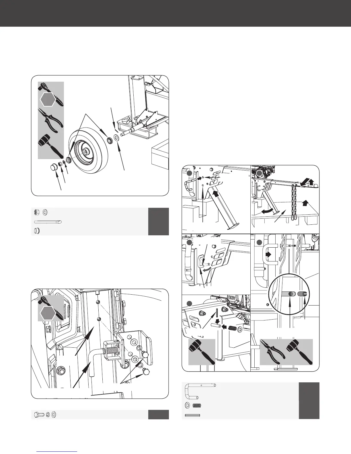
18. Follow the same procedure to assemble the other wheel.
(Follow steps 3 – 10 under wheel assembly.)
Wheel Washer (x1)
Roller Bearing (x2)
Cotter Pin (x1)
Axle Nut (x1)
Wheel Cap (x1)
Anti-dust Washer (x1)
M22 X 1
6
4 X 50 X 1
X 1
M10 X 25 X 2
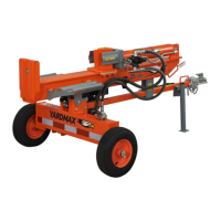
7
16 mm
32 mm
X 1
8
X 1
6 X 40 X 2
4
1
Upper Hole
2
Lower Hole
Wooden Support
U-shaped Lock Pin Hole
Roll Pin (x1)
Roll Pin (x1)
5
Lower Hole
U-shaped Lock Pin
3
YS2565PM01 - 1609
16
Gas Log Splitter
»
Operator’s Manual
Assembly
|
Figure 9
Figure 8
Figure 7k
65876US25M101.indd 16 2016/8/26 11:10:34