M12x35 (x8)
Inside Holes
Outside Holes
Log Cradle (Left)
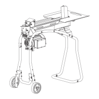
1. Align the holes on the left log cradle to the inside and lower holes
on the beam mounts. Insert the M12x35 bolts, at washers, nuts
and securely tighten.
2. Follow step 1 to assemble the right log cradle. (See Figure 14)
LOG CRADLES
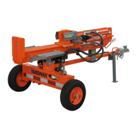
Place the work table over the holes in the log cradle and align
the 4 holes from the work table plate and log cradle. Insert
and tighten the M10x25 bolts, spring washers, at washers,
and nuts.
LOG TABLE (OPTIONAL)
Log Cradle (Right)
Outside
Holes
Inside
Holes
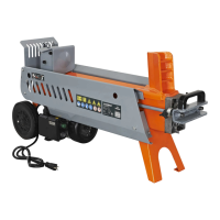
Refer to Figures 15a and 15b to install the work table. Remove
the bolts, at washers, and nuts from the inside holes. Move
the log cradle from the incline position to the horizontal
position. Align holes on the log cradle with the outside holes
on the beam mount. Reinstall bolts, at washers, and nuts.
1 2
1
2
Lower Hole
Upper Hole
Upper Hole
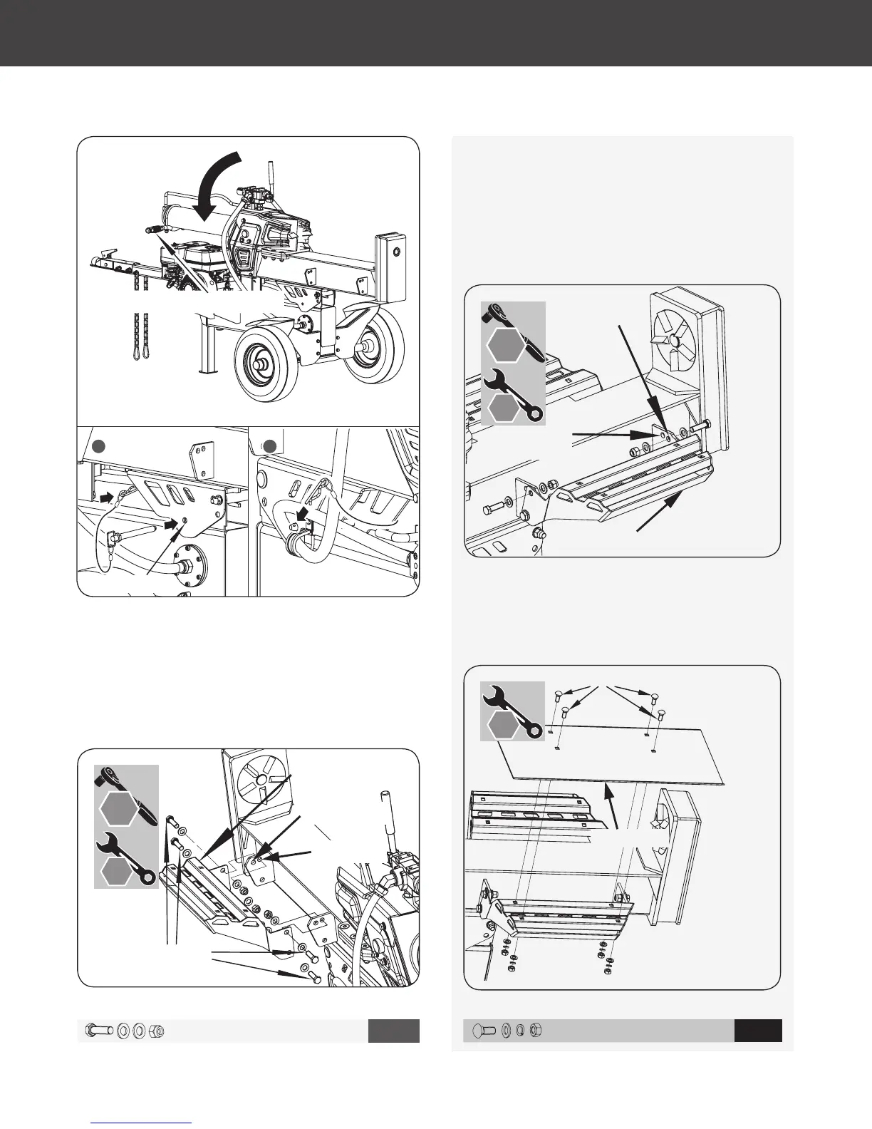
Hydraulic Cylinder Handle
M12 X 35 X 8
11
M10 X 25 X 4
12
16 mm
18 mm
19 mm
18 mm
19 mm
YS2565PM01 - 1609
18
Gas Log Splitter
»
Operator’s Manual
Assembly
|
Figure 15b
Figure 15a
Figure 14
Figure 13b
65876US25M101.indd 18 2016/8/26 11:10:35